
Sizing of Dust Separation Cyclones
Leith & Licht Method
Step-by-step calculation guide: How to design and rate a cyclone for gas-solid separation
Follow us on Twitter

Question, remark ? Contact us at admin@powderprocess.net
| Section summary |
|---|
| 1. Introduction: Leith & Licht Method |
| 2. Domain of Validity |
| 3. Cyclone Standard Geometries (Stairmand, Lapple, Swift) |
| 4. Leith & Licht Model: Step-by-Step Design Guide & Formulas |
| 5. Interactive Cyclone Sizing Calculator (#calc-app) |
| 6. Industrial Rules of Thumb & Operational Safety Limits |
| 7. Downloadable Cyclone Design Excel Calculation Tool |
Top 5 Most Popular
1. Pneumatic transport design guide
2. Ribbon blenders
3. Powder mixing
4. Hoppers design guide
5. Measuring degree of mixing
--------------

--------------
Top 5 New
1. Continuous Dry Mixing
2. Mixing speed
3. Mixer cycle time optimization
4. Batch / continuous mixing comparison
5. Energy Savings
1. Introduction
Leith & Licht Method
There are different methods published in the literature to design cyclones. The method presented on this page was developed by Leith & Licht in the 1970s. The calculation principle is based on a dynamic force balance on the particles that need to be separated in the vortex, accounting for turbulent back-mixing within the outer gas stream [Altmeyer]. From comparative studies of cyclone design methods published in academic literature, the Leith & Licht method provides an excellent analytical framework for evaluating fractional efficiencies and cut-off points without requiring complex computational fluid dynamics (CFD) [Altmeyer, Dirgo].
The method presented gives reliable preliminary results and should be utilized for equipment sizing and performance verification. A specialized cyclone vendor or engineering consultant should be consulted for final fabrication detailing.
Another cyclone design method (Lapple / Stairmand classic approach) is presented here to compare alternative calculation models.
2. Domain of Validity
In which conditions can the Leith & Licht method be used?
The model of Leith & Licht was validated against experimental pilot and industrial data within the following typical envelope [Altmeyer]:
- Gas volumetric flowrate: \(0.06 < V_0 < 0.13 \text{ m}^3/\text{s}\) (per cyclone body in primary test runs, scalable via standard dimensional similitude)
- Gas temperature: \(310 < T < 422 \text{ K}\)
- Static pressure: atmospheric to moderate pressure
- Solids loading: dilute to moderate dust concentrations (typically \(< 20 \text{ g/m}^3\))
3. Cyclones Standard Geometry
Standard Dimensional Proportions of Tangential Inlet Cyclones
Cyclone collection efficiency and hydraulic resistance are directly governed by internal dimensional ratios. Over decades of industrial testing, standard families of dimensions have been established (Koch and Licht, 1977; Lapple; Stairmand; Swift). These geometric proportions constitute the industry benchmark for standard tangential-entry cyclones.
| Standard Geometries for Cyclones with Tangential Inlet | |||||
| Standard Efficiency | High Efficiency | ||||
| Ratio | Lapple | Swift | Peterson-Whitby | Stairmand | Swift (HE) |
| Inlet Height: \(a/D\) | 0.5 | 0.5 | 0.583 | 0.5 | 0.44 |
| Inlet Width: \(b/D\) | 0.25 | 0.25 | 0.208 | 0.2 | 0.21 |
| Vortex Length: \(S/D\) | 0.625 | 0.6 | 0.583 | 0.5 | 0.5 |
| Gas Outlet Dia.: \(D_e/D\) | 0.5 | 0.5 | 0.5 | 0.5 | 0.4 |
| Cylinder Height: \(h/D\) | 2.0 | 1.75 | 1.333 | 1.5 | 1.4 |
| Cone Height: \((H-h)/D\) | 2.0 | 2.0 | 1.84 | 2.5 | 2.5 |
| Dust Outlet Dia.: \(B/D\) | 0.25 | 0.4 | 0.5 | 0.375 | 0.4 |
Table 1: Standard cyclone geometries for tangential inlet designs (Koch & Licht, 1977)
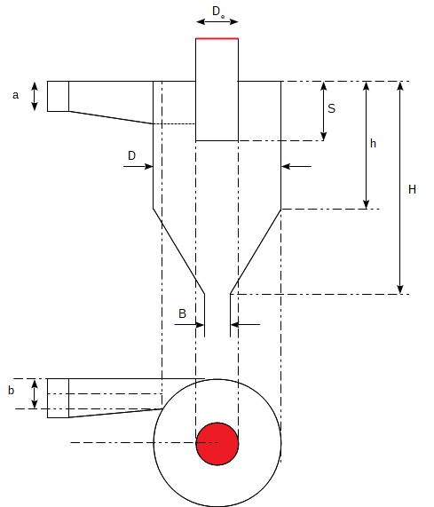
Figure 1: Cyclone geometry drawing and characteristic nomenclature
4. Leith & Licht Model: Step-by-Step Calculation Method
4.1 Gather Input Data
The calculation requires the gas operational state, particulate physical properties, and flow geometry:
- Inlet volumetric gas flowrate: \(V_0 \text{ (m}^3\text{/s)}\)
- Gas temperature \(T \text{ (K)}\) and operating pressure
- Gas density \(\rho \text{ (kg/m}^3\text{)}\) and gas dynamic viscosity \(\mu \text{ (Pa}\cdot\text{s)}\)
- Particle true density \(\rho_p \text{ (kg/m}^3\text{)}\) and representative particle diameter \(d \text{ (m)}\)
- Selected body diameter \(D \text{ (m)}\) and geometric ratios
4.2 Cyclone Dimensions
From the cyclone body diameter \(D\) and the selected family ratios (Table 1), calculate: inlet height \(a\), inlet width \(b\), vortex finder length \(S\), vortex finder diameter \(D_e\), cylinder height \(h\), overall height \(H\), and dust discharge diameter \(B\).
4.3 Natural Length \(l\) of the Cyclone
The natural length \(l\) represents the lowest boundary of the vortex spinning down into the conical hopper before reversing up toward the vortex finder:
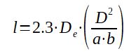
Note: If the computed \(l > (H - S)\), the vortex terminates at the dust discharge boundary, and \(l\) is set equal to \((H - S)\) in subsequent expressions.
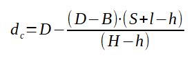
4.4 Cone Diameter \(d_c\) at Natural Length
The internal cone diameter at the lowest point reached by the vortex is given by linear geometric interpolation:
4.5 Vortex Exponent \(n\)
The tangential velocity distribution follows \(v_\theta \cdot r^n = \text{constant}\). Alexander's empirical correlation accounts for body diameter and gas temperature:

Where \(D\) is in meters and \(T\) is in Kelvin.
4.6 Cyclone Inertia Parameter \(\Psi\)
The dimensionless centrifugal inertia parameter characterizes the balance between centrifugal migration and Stokes viscous drag:
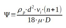
Where \(v_i = \frac{V_0}{a \cdot b}\) is the gas inlet velocity.
4.7 Cyclone Geometry Parameter \(C\)
Parameter \(C\) describes the effective volume and residence trajectory of the gas within the annular and conical chambers:

4.8 Cyclone Collection Efficiency \(\eta\)
The fractional collection efficiency for particle size \(d\) is calculated using the Leith & Licht modified exponential formulation:

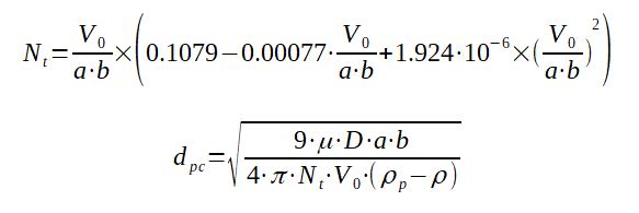
4.9 Calculation of Cut-Off Diameter (\(d_{pc}\) / \(d_{50}\))
The cut-off size \(d_{pc}\) (the particle aerodynamic diameter collected at 50% efficiency) is derived via the effective number of vortex turns \(N_t\):
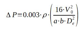
4.10 Calculation of Cyclone Pressure Drop (\(\Delta P\))
The gas pressure loss across the tangential inlet and central vortex finder tube is estimated using the Leith & Licht / Altmeyer relationship:
5. Interactive Cyclone Sizing Calculator
Calculated Results & Dimensions
🛠️ Practical Industrial Rules of Thumb & Safety Limits
- Inlet Velocity Window: Target gas inlet velocity \(v_i\) strictly between 15.0 and 22.0 m/s (50 to 72 ft/s). Velocities \(< 12 \text{ m/s}\) drop centrifugal separation force sharply, while velocities \(> 25 \text{ m/s}\) provoke severe wall erosion, particle attrition, and dust re-entrainment from the cone apex.
- Pressure Drop Tolerance: High-efficiency cyclones (e.g. Stairmand) typically operate between 1,000 and 1,800 Pa (4 to 7 in. w.g.). A pressure drop exceeding 2,500 Pa requires excessive booster fan electrical power and often signals an undersized body diameter.
- Hopper Discharge Sealing: Up to 15% efficiency loss occurs if the bottom dust discharge permits air in-leakage. Always use a counter-weighted double flap valve, an airtight rotary airlock valve, or an airtight discharge canister with pressure-balancing vents.
- ATEX & Dust Explosion Safety: Cyclones handling combustible organic or metallic powders (Kst > 0) generate high electrostatic charges due to high-speed swirling friction. The entire cyclone body, vortex finder, and hopper must be bonded and grounded to earth (\(R < 10\ \Omega\)) and fitted with certified explosion venting or suppression ducts where required by NFPA 68 / 69 or ATEX 2014/34/EU.
- Solids Loading Effect: At higher solids concentrations (\(> 50 \text{ g/m}^3\)), coarse particles form agglomerating descending ribbons that sweep fine particles into the hopper, actually increasing overall efficiency beyond dilute Leith & Licht predictions.
7. Leith & Licht Model Excel Calculation Tool
A downloadable spreadsheet version implementing the Leith & Licht formulas is available for engineering studies:
📥 Download Cyclone Design Excel / ODS Tool
Note: This engineering model is designed for preliminary sizing and academic rating. Always collaborate with a certified cyclone manufacturer to validate aerodynamic geometries for erosive, sticky, or high-temperature bulk solids.
References:
[Dirgo] Cyclone Collection Efficiency: Comparison of Experimental Results with Theoretical Predictions, Dirgo & Leith, Aerosol Science and Technology, 2007.
[Altmeyer] Comparison of different models of cyclone prediction performance for various operating conditions using a general software, Altmeyer et al., Chemical Engineering and Processing, 2004.
[Koch & Licht] New Approach to Cyclone Design and Specification, Koch, W.H. and Licht, W., Chemical Engineering, Vol. 84, pp. 80-88, 1977.