
Drum Dumper Systems
Drum rotating devices for bulk powder discharging & dust containment
Follow us on Twitter
Question, remark? Contact us at admin@powderprocess.net
| Section Summary | |||
|---|---|---|---|
| 1. Simple drum dumping stations | |||
| 2. Sealed drum dumpers & dust containment | |||
| 3. Drum discharging engineering equations | |||
| 4. Interactive Drum Dumper Sizing Calculator (#calc-app) | |||
| 5. Industrial rules of thumb & ATEX safety limits | |||
| 6. Equipment manufacturers | |||
| 7. Technical FAQ | |||
Bulk solids can be delivered in industrial drums (steel, fiber, or high-density plastic), serving as a practical intermediary container format between standard 25 kg bags and large 1000 kg Big Bags (FIBCs). Drums typically range from 50 to 220 liters (15 to 55 US gallons) and are widely favored for high-value active pharmaceutical ingredients (APIs), specialty fine chemicals, toxic additives, metal powders, food flavorings, and hygroscopic ingredients. The format offers excellent physical barrier protection and allows container re-use. However, safely discharging bulk powder from drums at high rates without exposing operators to ergonomic hazards or airborne dust poses significant engineering challenges.
This technical guide focuses on industrial drum dumping stations (also referred to as drum tippers, drum rotators, or drum discharge inverters). A crucial distinction is made between free-flowing bulk solids that generate minimal dust (such as coarse grains, masterbatch plastic pellets, and non-friable granules) and fine powders that aerosolize readily upon tipping.
1. Simple Drum Dumping Stations
If the bulk material exhibits high particle size and generates no or negligible dust during tipping, an open or semi-open simple drum dumper can be specified.
After manual or automated de-heading (removing the drum lid and clamping ring), the drum is rolled into a carriage cradle or hydraulic lift trolley. The carriage locks the drum in place, lifts it mechanically or hydraulically to the target discharge height, and tilts it beyond the angle of repose (typically 135° to 180° from vertical). A transfer chute guides the gravity-fed solid stream directly into a reception hopper, from which the material can be fed downstream via a rotary valve, screw feeder, or pneumatic conveying system.
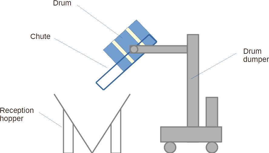
Figure 1 : Bulk solids simple drum dumper with open chute
While mechanically cost-effective and straightforward, simple open dumpers are strictly unsuitable for hazardous, potent, or dusty bulk powders. Tipping fine solids in an unsealed environment leads to massive dust clouds, occupational exposure limit (OEL) violations, product loss, housekeeping burdens, and dangerous ATEX/NFPA combustible dust atmospheres.
2. Sealed Drum Dumpers & Dust Containment
To eliminate fugitive particulate emissions and protect plant operators, equipment manufacturers provide sealed drum dumping stations featuring dust containment cones and inflatable or elastomeric seals.
In a sealed discharge setup:
- The drum is positioned on the lift platform, and its lid is removed.
- A sanitary conical discharge adapter equipped with an elastomeric seal ring is clamped pneumatically or mechanically over the open lip of the drum.
- The tip of the cone is fitted with a sanitary butterfly valve, iris valve, or split butterfly valve (SBV) for high-containment toxic applications.
- The clamped assembly is inverted 180°, placing the cone apex downward over the reception hopper.
- The discharge cone docks into a sealed receiving port on the hopper cover (often utilizing an inflatable seal or containment split-valve).
- The isolation valve opens, enabling controlled gravity discharge into the receiving vessel under dust-tight isolation.
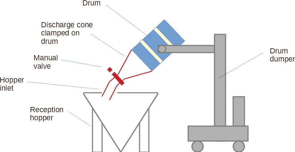
Figure 2 : Sealed drum dumper with clamped cone and discharge valve for dusty materials
To prevent pressure surges inside the receiving hopper as powder rushes in, the reception hopper must incorporate an integrated venting dust filter or active local exhaust ventilation (LEV) system sized to accommodate the displaced air volume.
Top 5 Most Popular
1. Pneumatic transport design guide
2. Ribbon blenders
3. Powder mixing
4. Hoppers design guide
5. Measuring degree of mixing
--------------
 --------------
Top 5 New
1. Continuous Dry Mixing
2. Mixing speed
3. Mixer cycle time optimization
4. Batch / continuous mixing comparison
5. Energy Savings
3. Drum Discharging Engineering Equations
Designing a drum dumping system requires sizing the hydraulic lifting power, estimating powder flow through the cone orifice, determining hourly throughput cycle times, and specifying the displaced air extraction rate for dust control.
3.1 Powder Payload & Total Lift Weight
The total mass \(M_{\text{gross}}\) handled by the lift carriage includes the powder payload, drum container, and the tipping cradle/cone hardware:
\[ m_{\text{powder}} = V_{\text{drum}} \cdot \phi_{\text{fill}} \cdot \rho_{\text{bulk}} \] \[ M_{\text{gross}} = m_{\text{powder}} + m_{\text{drum}} + m_{\text{cone}} \]Where \(V_{\text{drum}}\) is the drum nominal internal volume, \(\phi_{\text{fill}}\) is the volumetric fill fraction (\(0.80 - 0.95\)), \(\rho_{\text{bulk}}\) is the powder bulk density, \(m_{\text{drum}}\) is the empty drum tare weight (typically \(15 - 22\text{ kg}\) for steel, \(4 - 9\text{ kg}\) for fiber/plastic), and \(m_{\text{cone}}\) is the clamping cradle and cone adapter weight.
3.2 Hydraulic / Mechanical Lifting Power
To lift the gross load through elevation height \(H\) in lifting time \(t_{\text{lift}}\), the required hydraulic power \(P_{\text{hyd}}\) accounting for mechanical-hydraulic system efficiency \(\eta\) (typically \(0.65 - 0.75\)) is:
\[ P_{\text{hyd}} = \frac{M_{\text{gross}} \cdot g \cdot H}{t_{\text{lift}} \cdot \eta \cdot 1000} \quad [\text{kW}] \]3.3 Gravity Discharge Orifice Flow Rate (Modified Beverloo Correlation)
When the clamped cone valve is opened, gravity discharge rate \(W_{\text{discharge}}\) through a circular cone orifice of diameter \(D_o\) can be approximated by:
\[ W_{\text{discharge}} = C \cdot \rho_{\text{bulk}} \cdot g^{0.5} \cdot (D_o - k \cdot d_p)^{2.5} \]Where \(C \approx 0.58\) for typical conical hoppers, \(k \approx 1.5 - 2.0\) is the particle shape boundary factor, and \(d_p\) is mean particle size. For fine powders (\(d_p \ll D_o\)), this yields an estimated powder discharge time:
\[ t_{\text{discharge}} \approx \frac{m_{\text{powder}}}{W_{\text{discharge}}} \]3.4 Air Displacement Venting Rate
As solids drop into the sealed hopper, an equivalent volumetric displacement occurs. Falling particles also drag boundary layer air into the vessel. The minimum dust venting rate \(Q_{\text{vent}}\) required to prevent vessel pressurization and dust blowback is calculated as:
\[ Q_{\text{vent}} = \left(\frac{m_{\text{powder}}}{\rho_{\text{bulk}} \cdot t_{\text{discharge}}}\right) \cdot (1 + k_{\text{entrain}}) \cdot 3600 \quad [\text{m}^3/\text{h}] \]Where \(k_{\text{entrain}}\) is the induced air entrainment coefficient (\(0.50 - 1.20\) depending on drop height).
3.5 Total Operating Cycle Time & Hourly Throughput
Total cycle time \(T_{\text{cycle}}\) combines positioning, clamping, lifting, discharging, lowering, and unclamping:
\[ T_{\text{cycle}} = t_{\text{load}} + t_{\text{lift}} + t_{\text{discharge}} + t_{\text{lower}} + t_{\text{unload}} \quad [\text{seconds}] \] \[ \text{Throughput} = \left(\frac{3600}{T_{\text{cycle}}}\right) \cdot m_{\text{powder}} \quad [\text{kg/h}] \]⚡ Drum Dumper Sizing & Dust Venting Calculator
🏭 Industrial Best Practices, ATEX & Safety Limits
- Cone Angle Selection: Use a minimum hopper cone slope of \(60^\circ\) from horizontal for free-flowing powders and \(\ge 70^\circ\) with smooth finish (Ra \(\le 0.8\,\mu\text{m}\)) for cohesive solids to guarantee mass flow and avoid funnel flow ratholing inside the drum adapter.
- ATEX / NFPA 652 Grounding: Steel drums, clamping cones, and mobile carriages must have verified grounding interlocks (< 10 \(\Omega\)). Never use standard insulative polyethylene drum liners with low-MIE (Minimum Ignition Energy) powders; specify antistatic or conductive dissipative liners with earthing clips to eliminate brush discharges.
- Air Displaced Surge Control: When opening a large 200 mm cone valve into a sealed receiving hopper, sudden solids drop creates a transient positive pressure peak. Provide a surge plenum or an appropriately sized hopper breather filter with an active face velocity \(\le 1.0\text{ m/min}\) to avoid blowing powder past seals.
- Containment Performance Target (OEL Bands): Standard clamping cones achieve OEB 2 / OEB 3 containment (\(10 - 100\,\mu\text{g/m}^3\)). For highly potent APIs requiring OEB 4 or OEB 5 (\(< 1\,\mu\text{g/m}^3\)), specify split butterfly valves (SBV) with active extraction wash-rings or glovebox isolator dumping stations.
- Ergonomic & Structural Limits: Standard hydraulic drum tippers are rated for \(350 - 450\text{ kg}\) gross load. For heavy powders (dense metal powders or wet cakes where bulk density exceeds \(1500\text{ kg/m}^3\)), verify structural frame torsional rigidity and dual-cylinder hydraulic lock valves to prevent uncommanded descent during inversion.
6. Companies Manufacturing Drum Dumpers
Leading global manufacturers specializing in industrial drum rotators and contained dumping stations include:
- Palamatic Process: Contained drum tipping stations, glovebox drum discharging, and pneumatic docking cones.
- De Dietrich Process Systems: Containment systems, glass-lined and sanitary powder transfer solutions.
- Flexicon Corporation: Sealed drum dumper systems, tip-trak dischargers with integral dust collection.
- STS Trolleys: Specialized ATEX-certified hydraulic mobile drum lifting and tipping machinery.
- Volkmann & Glatt: High-containment pharmaceutical drum lifting and vacuum transfer stations.
Note: PowderProcess.net maintains complete editorial independence and has no commercial affiliation with these equipment suppliers.
7. Frequently Asked Questions (FAQ)
Q1: What is the primary difference between open and sealed drum dumpers?
Open drum dumpers invert the container directly over an open hopper or chute. They are economical but restricted to non-dusty products like pellets and coarse grains. Sealed drum dumpers clamp a conical adapter with a dust-tight elastomeric gasket and a valve directly to the drum rim before inverting, enabling safe discharge of hazardous, toxic, or airborne fine powders without dust leakage.
Q2: How do you size the dust collection and venting filter for a drum dumper?
The venting airflow must equal the bulk volume of powder dropping per second plus the induced interstitial air drawn down with the falling stream. Applying an entrainment factor of \(1.0 - 1.8\), the filter surface area must ensure the filtration air-to-cloth ratio (face velocity) remains below \(1.0 - 1.2\text{ m/min}\) (\(3.3 - 4.0\text{ ft/min}\)) to prevent fine dust from blinding the filter cartridges or blowing through gasket seals.
Q3: How can cohesive powders that bridge inside the drum be reliably discharged?
Cohesive powders frequently arch inside cylindrical drums or at the cone transition. Contained drum dumpers address this with pneumatic vibrators mounted directly on the discharge cone, motorized gentle drum massagers/paddles to break powder caking before inverting, fluidizing aerator pads, or internal mechanical lump breakers located above the discharge valve.