
Dust Aspiration and Collection Systems (Dust Control) : an
overview
Engineering Guide for design and operation of dust collectors for efficient dust extraction
Follow us on Twitter
Question, remark ? Contact us at admin@powderprocess.net
| Page summary |
|---|
| 1. Definition of a
dust aspiration system |
| 2. Single point
dust collection |
| 3. Centralized
dust aspiration system |
| • Interactive Hood
& Duct Sizing Calculator |
| 4. Common problems with dust
collection systems |
| 5. Monitoring a dust collection
system |
| 6. How to buy a dust collector ? |
Industrial dust collectors are system allowing to extract dust at one or several location, transport it with the air flow and collect it in a receiver, often equipped with a filtration system, before releasing clean air. Those systems are critical to ensure both a safe working area and making sure the air released in the environment is clean. The Engineering Guide presented in this page gives detail on the design of dust collection systems, their performance and how to solve problems that factory usually experience with those systems.
1. Definition of a dust collection system
Types of dust collection systems / What is a dust aspiration system ?
All industries having to deal with solids have also to deal with dust : powder processing industries of course, but also plastic industries, wood industries, mechanical workshops or even new technologies like addition manufacturing which is handling polymer or metal powders. It is crucial when handling dusts to be able to contain them for reasons of cleanliness, hygiene or safety (avoid that the operator inhales the dust and / or that dust explosion (ATEX) risks are created). Systems to collect dust must then be designed, installed and operated properly. Such systems are typically referred to as Dust Aspiration Systems, Dust Collection Systems or Dust collectors.
Dust aspiration systems can have different design and different sizes. Typically, powderprocess.net distinguishes 2 categories :
- Local dust aspiration system : small system mounted locally, directly on the equipment where the dust emission can happen
- Centralized dust collection system : larger system allowing to collect powder at different locations
Both types have in common to have a fan to suck air and carry dust away from the working area, and a filter to collect the dust.
Centralized dust collection systems have in addition some pipes / ducts to bring air and dust to a collecting hopper. The collecting hopper is typically using a filter (baghouse or cartridge) to capture the dust and make sure that clean air is rejected. To be noted that other processes can be used as dust collectors : cyclones, scrubbers, electrostatic precipitators. These are however bigger systems beyond the scope of this page, more focusing on capturing small to medium localized emissions observed at a tipping station, for example, or when powder is poured out of a vessel.
Looking for other dust aspiration systems, or specific components ? Check these other pages out : FILTERS, GAS / SOLIDS SEPARATION. By PowderProcess.net
Top
5 Most Popular
1.
Pneumatic transport design guide
2. Ribbon blenders
3. Powder mixing
4. Hoppers design guide
5. Measuring degree of
mixing
--------------
 --------------
Top 5 New
1. Continuous Dry Mixing
2. Mixing speed
3. Mixer cycle time
optimization
4. Batch
/ continuous mixing comparison
5. Energy Savings
2. Single point dust collection
2.1 How does it work ?
A solution that is particularly adapted to emissions of dust due to the manipulation of opened bags, typically on bags tipping stations, is to have a dust aspiration system directly mounted on the equipment from where the dust emission will happen.
Such a system is made of :
- A filter that will collect the dust
- A fan that will provide the driving force to suck air located at the point of emission of dust and carry the dust with it
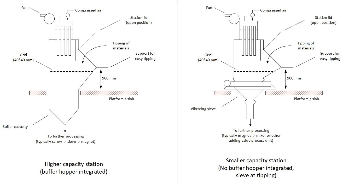
Figure 1 : examples of bags tipping stations with top mounted dust aspiration
If it is possible to close the equipment once the operation generating dust is completed, then the use of a pulse jet filter is a good choice as it will allow to unplug the filter and let the dust fall back in the process once the operator has completed the tipping, thus avoiding waste of materials.
As for all dust aspiration system, the sizing of the fan and of the filter is of great importance for ensuring the good performance of the system, i.e. to make sure dust is properly captured.
In the case of a tipping station, the fan must be strong enough to ensure that the air velocity through the opening is min ~0.5 m/s, with the filter sized so that the pressure drop is minimal (few mbar).
2.2 Pros and cons of a localized dust aspiration system ?
Table 1 : pros and cons of a
localized dust aspiration system
| Pros | Cons |
| Compact system No duct Fits well on bag tipping stations Possible to recycle the captured dust directly |
Only 1 system per equipment, thus can be costly if many sources of emission |
3. Centralized dust collection system
3.1 What is a central dust aspiration system ?
A central dust aspiration system is located away from the source of dust emission and connected to it thanks to ductworks that will carry air and dust to the central collector. It is then possible to connect several equipment to a single centralized extraction system. This is particularly attractive for example in the case of some mechanical workshop having several machines that can generate dust, or if a manufacturer has a high number of tipping stations installed close by one another. Typical applications of these kind of system are the following :
- Woodworking
- Metal cutting, grinding
- Material handling (tipping stations)
The system is made of a dust collector, which is a hopper equipped with a filter and connected to a fan that will suck the air from the different collection points to the receiving hopper. As for the localized system explained above, it is a good practice to have the filter equipped with an auto-cleaning system, typically pulse jet, in order to extend the life of the filter.
If the central dust extraction system is connected to several equipment, which is normally the case as it allows to make some investment savings vs having 1 system for 1 source of dust, the design of the ducting system is of prime importance. Indeed, the higher the number of ducts, the most difficult it is to ensure a good suction power is evenly spread for all equipment.
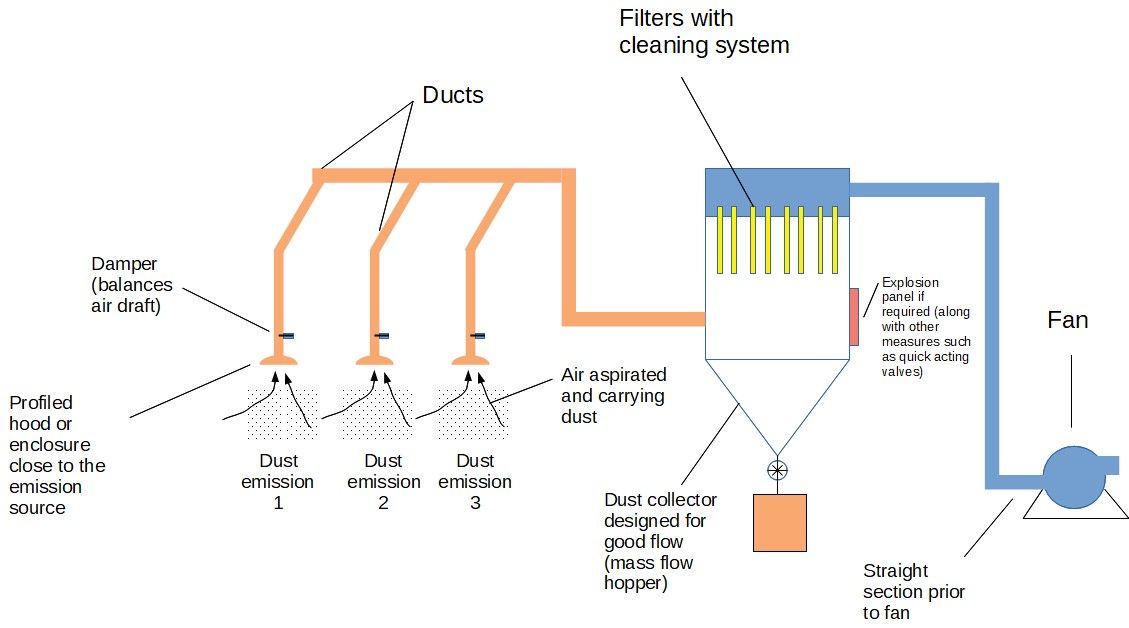
Figure 2 : example of central dust
collection system
3.2 How to design an efficient dust collection system ?
Typical design requirements are the following :
- The air velocity at the extraction point (pick-up velocity) must be high enough to capture the dust
- The air velocity in the ducts must be high enough to allow to carry the dust to the reception hopper
- As a consequence, the fan must be designed to ensure those velocities, and the filter must be sized according to the max capacity of the fan
- The whole ducting system must be well balanced in order to avoid to have some emission points without enough air for a proper aspiration. While balancing dampers or blast gates are widely used, designing an inherently balanced system by branch diameter sizing is the preferred industrial practice [Maynard, Osborn].
In addition, the following design recommendations can be considered :
- Ducting must be as short and straight as possible in order to reduce the pressure drop (thus the size of the fan and the energy consumption)
- The velocity must neither too high (energy waste, some risks of attrition) nor too low (deposits of dust leading to duct blockages)
- The system can be automatized, with a fan on frequency drive, so that the suction power is adapted to the need (energy savings), if only few collection points are actually in use at a given time
- It must be thought in advance how the dust will be handled : is it possible to collect it in bags for example, or, better, is it possible to recycle it directly back to the process
3.3 Pros and cons of a central dust collector ?
Table 2 : pros and cons of a central dust aspiration system
| Pros | Cons |
| Well adapted to multiple sources of dust emission | Maintenance of the dust collector and discharge is required Balancing of the ducting can be delicate, and blast gates are prone to unauthorized operator tinkering or dust jamming ATEX risk to be considered in the installation and in the receiver May not be easy to recycle the dust collected if different materials are collected then mixed in the collector |
3.4 Pick-up hood and pick-up velocity
This is a basic of dust aspiration, but actually not so often performed properly on the field. In dust collection engineering, successful hood design follows the "3-Cs" principle (Containment, Capture, Control), which is also highlighted in NFPA dust control standards [Osborn] :
- Containment : Enclose the dust generating point as much as practical to minimize air volume requirements, but without over-containing in a way that creates internal dust accumulation ledges.
- Capture : Provide sufficient airflow and capture velocity right where dust particles are emitted to pull them into the hood. Crucial pitfall to avoid : Connecting an aspiration hood directly to a completely sealed, enclosed vessel (such as a mixer, bin, or chute) with no incoming air relief. Without an intentional air inlet/make-up pathway, air cannot flow into the hood; with zero airflow, there is zero air velocity, meaning zero dust capture !
- Control (Convey) : Design smooth transitions from the hood mouth into the ductwork so air velocity accelerates smoothly and carries dust without dropping it out.
The 1st thing is to have a proper hood design to have an efficient aspiration :
- It is 1st better to have a profiled hood, adapted to the application, than just a tube. It can be required to have an enclosure in order to have efficient capture [SHAPA]
- The hood must be positioned close to the dust emission source : the highest velocity is of course at the duct entry when the diameter is narrower, but it must be kept in mind that the velocity will be 70% lower at ~1/2 diameter of the pick-up point while it is 90% lower at 1 diameter [Maynard]
- The hood must be positioned in a way that it does not pull the dust to the operator face [Constance]
The pick-up velocity must then be adapted to the application, as requirement will vary according to the nature of the dust to capture, but also the dynamic conditions of the capture, i.e. if the dust is almost static, or if there are drafts that are pulling the dust away from the collection point. The following capture velocities can be found in the literature [SHAPA] :
Table 3 : recommended dust capture
velocities
| Emission type | Pick-up velocity | Examples |
| No velocity | 0.3-0.5 m/s | Vapors, welding fumes |
| Low velocity | 0.5-1 m/s | Powder weighing, packaging, laser cutting |
| High velocity | 1-2.5 m/s | Plasma cutting, high speed conveyor belt |
| High force | 2.5-10 m/s | Grinding |
It is possible to estimate the flow required considering the advised pick-up velocity and the distance of the hood entry to the dust emission source thanks to the following DallaValle / SHAPA formula [SHAPA] :
\[ Q = V \cdot (10 X^2 + A) \]With :
- \(Q\) = required air flow (\(\text{m}^3/\text{min}\) or \(\text{CFM}\))
- \(V\) = required capture velocity (\(\text{m/min}\) or \(\text{fpm}\))
- \(X\) = distance to dust emission source (\(\text{m}\) or \(\text{ft}\))
- \(A\) = open hood face area (\(\text{m}^2\) or \(\text{ft}^2\))
Note: For a flanged hood opening, air requirement is reduced by approximately 25%: \(Q_{\text{flanged}} \approx 0.75 \cdot V \cdot (10 X^2 + A)\).
3.5 Air velocity in ducts
The air velocity in ducts should neither be too high (energy waste, risk of abrasion), nor too low (dust build-up in the pipes). Depending on the dust type, the air velocities are recommended around 10 m/s for fumes and in between 15 (light dust) and 23 m/s (coarse particles) for solids ([SHAPA], [Maynard]).
\[ v_{\text{duct}} = \frac{4 \cdot Q}{\pi \cdot D^2} \] \[ P_{\text{fan}} = \frac{Q \cdot \Delta P}{3600 \cdot 1000 \cdot \eta_{\text{fan}}} \]1. Hood Geometry & Capture
2. Duct & Filter Sizing
Dust Collection Sizing Results
| Engineering Parameter | Calculated Value | Design Assessment |
|---|---|---|
| Suction Airflow Rate (\(Q\)) | -- | -- |
| Duct Conveying Velocity (\(v_{\text{duct}}\)) | -- | -- |
| Required Filter Cloth Area (\(A_{\text{cloth}}\)) | -- | -- |
| Estimated Fan Shaft Power (\(P_{\text{fan}}\)) | -- | -- |
⭐ Powder Handling Best Practices: Duct Velocity & Baghouse Design
- Saltation & Settling Limits: Always design horizontal ducts above the saltation velocity. Maintain at least 15 m/s (3,000 fpm) for light organic powders (starch, cocoa) and 20–22 m/s (4,000–4,300 fpm) for heavy or moist powders (sand, limestone).
- Branch Junctions: Never enter the main header at a 90° angle. Use 30° to 45° lateral entries to preserve dynamic velocity pressure, avoid 3x to 5x pressure penalties, and eliminate dead zones where dust accumulates [Osborn].
- Filter Differential Pressure (\(\Delta P\)): Standard baseline across clean pulse-jet filters is 5 to 8 mbar (2 to 3.2 in. w.g.). Cleaning pulses should cycle when \(\Delta P\) reaches 10 to 12 mbar. Persistent \(\Delta P \ge 15\) mbar (6 in. w.g.) indicates irreversible filter blinding requiring media replacement.
- ATEX / NFPA Explosion Protection: Fine dust clouds inside baghouses represent high explosion risks. Always verify dust Kst and Pmax values, fit explosion venting panels ducted outdoors or certified flameless vents, and install mechanical isolation valves in the suction ductwork.
3.6 Ductwork
Ducts conveying the air and powder must be studied in detail during the conception of the dust collection system. Indeed, it is very important to make sure that some design aspects have been correctly taken into account :
- The diameter of the piping must be such that the required air velocity is reached.
- Avoid "Plenum Manifolds" : A widespread design failure is running a single, large, constant-diameter main trunk with smaller branch ducts tapped into it along the way. Because airflow volume changes at every pickup branch, a constant-diameter main trunk will experience drastic drops in air velocity in upstream sections, creating dangerous zones where combustible dust settles out. A properly engineered manifold must be tapered (step-reduced in diameter) to guarantee transport velocity throughout [Osborn].
- The pressure drop must be minimized (will allow to reduce the size of the fan and make savings both at investment and in electricity spent for running the system).
- The construction of the duct must reduce the risks of leakage.
- System balancing : "Balanced-by-Design" vs "Artificial Balancing" : Many systems resort to "artificial balancing" using blast gates, dampers, or orifice plates. While blast gates look flexible, in operating plants they frequently fail : dust accumulates behind the slide gate, vibration moves them, or operators tamper with them, which throws the whole network out of balance. [Maynard] and [Osborn] strongly recommend the Balanced-by-Design method : branch duct diameters and elbows are precisely calculated using fluid mechanics so that system static pressures and required conveying velocities naturally balance without relying on gates. If blast gates must be used, they must be lockable, sealed, and cleaned regularly.
- Junction angles : Branches should always enter the main duct through an inclined entry (typically 30° to 45°), never at a straight 90° T. A 90° tee connection produces 3 to 5 times higher energy loss and causes severe air turbulence that disrupts conveying velocity downstream [Osborn].
3.7 Fan and filter
Reaching the design air pick-up velocities and conveying velocities in ducts require to size properly the fan and the filter according to the air flow requirement and the pressure drop that will be generated through the system.
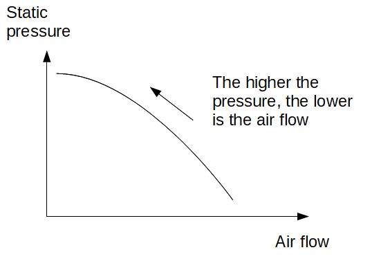
- A fan is a centrifugal air mover. As such, one must be careful to that the airflow generated is not constant with the pressure, which is normally the case with a positive displacement blower like a lobe blower. It means that if the pressure drop in the ducts is not properly evaluated, or if operators close too much the dampers, the total air flow through the fan will decrease and thus prevent to have a good capture and conveying of the dust.
- Fan curve slope (Steep vs Flat curve) : When selecting a centrifugal fan, the shape of its performance curve is critical. If a fan has a flat curve, a slight increase in filter pressure drop (e.g. 2 to 5 mbar as dust cake builds) will cause airflow to collapse drastically by hundreds or thousands of m³/h, causing hoods to starve. Sizing for a fan with a steep performance curve ensures that as the filter cakes, the fan naturally delivers stable airflow across the entire pressure range [Osborn].
- Fan impeller type : For fans installed on the clean air side of the dust collector, backward-inclined or backward-curved wheels are preferred because they achieve superior energy efficiency (often 75-85%). Radial or radial-tip wheels are typically reserved for heavy material-handling applications on dirty airstreams.
- In order to generate energy savings, the fan can be equipped with a frequency drive that will vary the speed according to the actual demand. It however requires some degree of automation but the payback is usually worth it.
- A section of straight pipe is recommended at the inlet of the fan [Constance], if the inlet of the fan is made of an elbow, the flow of air may not be constant and the fan can suffer from pulsation and lower airflow than expected.
- The filter must be sized large enough in order to reduce the pressure drop and the frequency of maintenance (changing of filters) required.
- As explained in powderprocess.net page on filtration, the baghouse or cartridges must be sized with a proper air to cloth ratio (filtration velocity), which will ensure a lower pressure drop and then a better performance of the whole system. As a rule of thumb, filter velocities should rarely exceed ~0.45 m/min (~1.5 fpm) for cartridge collectors, and ~1.5 m/min (~5.0 fpm) for baghouse collectors handling dry powders [Osborn].
- The filter must be equipped with an automatic cleaning system which very often takes the shape of a pulse jet system : compressed air is injected backwards to the filter. The air flow and the deformation of the filter allow to make dust fall from the filter and clean it. The cleaning can be triggered according to a timer, or according to the pressure drop (may be better from an energy point of view). Pressure drop triggering cleaning are typically 8-10 mbar g. Filter end-of-life : when a sustained differential pressure reaches 15 mbar (~6 in. w.g.) and cannot be brought down by pulse-jet cleaning, the filter elements are blinded and must be replaced [Osborn].
3.8 Dust explosion protection
Dust can lead to explosion if a dust cloud is submitted to an ignition source. Dusts, according to their nature, have different MIE making them more or less sensitive to explosions. However, one must consider that dusts are usually fine, which is decreasing the MIE and make dust collection a clear potential hazard for the factory.
As a consequence :
- A dust hazard analysis (DHA, DSEAR, ATEX risk analysis) is mandatory.
- All good practices such as electrical grounding of each and every part of the dust collection system are mandatory. Operators must be particularly careful on the duct, flexible, and support of the filters.
- Depending on the dusts handled, the size and quantity hold in the collector, it may be necessary to protect the dust collector with an explosion panel or a suppression system, and make sure that the explosion cannot propagate back into the ducts.
There are many examples of explosion in dust collectors, this topic must be taken with utmost seriousness by vendors and operators of the systems.
3.9 Hopper discharge and collected material evacuation
A central dust collector is an air-solid separator, not a storage bin. One of the most recurring failure points in industrial installations is the inability to evacuate captured material out of the receiver hopper in a timely, continuous manner [Osborn].
- Avoid undersized discharge openings : Trying to discharge fine dust from a large rectangular or pyramid hopper (e.g., 2 m x 2 m base) through a small 150 mm (6″) or 200 mm (8″) rotary airlock creates an extreme bottleneck. Fine powders easily arch or bridge over small inlets.
- Recommended discharge configuration : For medium to large hoppers, best practice is to install a minimum 250 mm to 300 mm (10″ to 12″) rotary valve, or ideally a flared-trough screw conveyor spanning the full bottom of the hopper that discharges directly into an airlock valve.
- Discharge drive interlocks : Rotary airlocks and discharge screw conveyors should be fitted with zero-speed switches. If an airlock motor trips or a drive chain breaks, collected dust will quickly accumulate up into the clean-air pleats or filter bags, choking the airflow and causing severe filter damage.
4. Common problems with dust extraction systems
Table 4 : common problems with centralized dust collection systems
| Issue | Root cause and action |
|---|---|
| Dust not well aspirated | Pick-up velocity is too low : check the airflow, make sure the aspiration duct has a hood / enclosure and is close enough to the dust source, check if a damper has moved. Check closed vessels : verify that aspirated enclosed bins/mixers have an engineered air make-up intake so air can actually flow into the hood. |
| Build up in ducts | Air velocity in the ducts is too low : check the fan airflow, verify filter, check adequacy duct diameter / fan air flow. Check duct geometry : verify manifold is properly tapered and not an oversized plenum; inspect 90° junctions that cause high turbulence. |
| Dust backing up into filter chamber | Discharge bottleneck or stalled airlock : check rotary valve size (avoid small 150 mm valves on large hoppers), verify rotary valve rotation (zero-speed switch), inspect hopper walls for powder bridging or ratholing. |
| High energy consumption | Fan always at high speed even if no requirement : automatize the system with fan on VFD |
| Too much pressure drop through filter | Filter is clogged : check pulse-jet cleaning compressed air pressure and pulsing interval. If pressure drop remains high (> 15 mbar / 6 in. w.g.) despite pulsing, filters are blinded and must be replaced. |
5. Monitoring a dust collection system
Problems can be anticipated and avoided, or the troubleshooting can be facilitated, if the dust filtration and collection system is properly instrumented and monitored. In particular, tracking the "Golden Trio" of operating parameters (Fan Motor Amps, Filter Differential Pressure, and Fan Inlet Static Pressure) provides an instant diagnosis of system health [Osborn] :
- Fan motor current (amperage) : Centrifugal fan motor amperage correlates directly with air mass flow (CFM / m³/h). In a clean system with new filters, airflow is highest and motor amperage peaks. When filters blind, ducts clog, or dampers close, static pressure increases and fan motor amperage drops. Monitoring amps is a very simple, low-cost way to detect airflow loss.
- Filter pressure drop measurement (\(\Delta P\)) : It is the essential data to follow up the performance of a dust filter. If the pressure drop is increasing above a certain threshold, it means that the filters are plugged. Trending the pressure drop through the filters is also helpful to detect specific incidents : if the pressure drop jumps suddenly, the auto-cleaning system may have failed ; on the contrary, if the pressure drops suddenly, a filter bag may have ruptured leaving the air, and the dust, go through without resistance. Filters should be replaced when sustained differential pressure reaches ~15 mbar (6 in. w.g.).
- Fan inlet static pressure (relative to atmosphere) : Measuring negative pressure right before the fan inlet tells the total system resistance. Combined with the filter \(\Delta P\), it tells the maintenance team whether an airflow problem is due to loaded filters or an obstruction in the ductwork.
- Air flow measurement : The capacity to suck the air at the different collection points and carry it to the central filter is based on the air velocity. If the air flow (thus velocity) is too low, the dust collection will not be efficient and, for the dust still aspirated, it will not be conveyed properly leading to an accumulation in the ducts (potential dust explosion risks). Making sure the air flow is always optimal is thus a key indicator of the performance of a system.
- Compressed air pressure measurement : For the filters using a compressed air pulse jet system for cleaning the filters, it is important to make sure the pressure of the cleaning compressed air is set properly (typically 5 to 7 bar g). If too low, the air flow will not be sufficient to dislodge the dust accumulated on the filter. If too high, repeating pulsing can damage the filter and lead to a leakage of dust.
- Level sensor and zero-speed switches in collection hoppers : The dust collected on the filters is falling back in the hopper during the cleaning cycle. The dust being very fine, it has likely a poor flowability which can lead to bridging or ratholes in the hoppers, causing an increase of the level which ultimately reaches the filter and forces a stoppage. Having level sensors combined with zero-speed switches on rotary valves / screw conveyors detects equipment stalls before dust fills the hopper up to the filter elements.
6. How to buy a dust collector ?
What are the dust collector suppliers ? What to know before buying a dust collector ?
The design of a well performing dust collector is not straightforward, it requires a careful design that has to be done by the dust collector supplier. It is thus critical to contact one (or better, several to be able to compare offers) dust collector supplier and give this company as many information as possible on the application : nature of the dust, PSD, one or several points of emission, how is emitted the dust, dust explosion characteristics / toxicity of the dust...etc... The manufacturer of the dust collector will then be able to make an informed proposal for a system that will satisfy the user.
Here are some examples of dust collector suppliers :
- Aspi Ouest
- Nederman
- Donaldson
- ACT dust collectors
- Camfil
- Delfin (small systems, vacuum cleaner based)
(Note that PowderProcess.net has no relation with those companies)
Source
[Maynard] Six key considerations for proper dust collection system design, Maynard, PBE, 2018
[Constance] Getting it right the next time, Constance, PBE, 2019
[SHAPA] 10 Key steps for comparing dust extraction systems proposals, Whitehead, SHAPA, 2002
[Osborn] 7 Reasons Dust Collection Systems Fail, Osborn, Powder & Bulk Solids, 2021