
Flexible Screw Conveyors
Design, Capacity Calculation & Sizing for Flexible Screw Conveyors
Follow us on Twitter
Question, remark ? Contact us at admin@powderprocess.net
| Page summary |
|---|
| 1. Introduction : flexible screw conveyors |
| 2. Design and Working Principle of Flexible Screw Conveyors |
| 3. Interactive Sizing & Motor Power Calculator (#calc-app) |
| 4. Mathematical Engineering Formulas |
| 5. Comparison with other bulk handling systems |
| 6. Practical Plant Engineering Rules & Wear Prevention |
| 7. Cleaning, Maintenance & Troubleshooting |
| 8. Flexible screw conveyors manufacturers |
| 9. Frequently Asked Questions (FAQ) |
1. Introduction : flexible screw conveyors
What is flexible screw conveyor ?
A flexible screw conveyor is a mechanical conveying system designed to transport bulk solid materials (powder, pellets, granulates...) within a factory. The transportation can be horizontal, inclined, or a combination of both with curves or bends.
Flexible screw conveyors are used for relatively short to medium distances (typically 3 to 10 m, sometimes up to 15-20 m in specialized configurations).
2. Design of flexible screw conveyors
Flexible screw conveyors characteristics
As for a standard screw conveyor, the elements constituting a flexible conveyor are:
- Outer polymer or flexible tube
- Shaftless steel screw flight (spiral)
- Drive unit (electric gearmotor)
- Seals and bearings (typically positioned outside product flow)
- Inlet charging hopper and discharge head
The main differences are in the design of the tube and the screw flight. The tube is made of semi-rigid plastic material, typically ultra-high-molecular-weight polyethylene (UHMW-PE) or special polyamide (PA12), which allows it to bend smoothly around obstacles according to the factory layout. The screw flight is made in high-strength carbon or stainless steel and is shaftless (coreless), giving it the flexibility needed to rotate smoothly along curved paths without intermediate hanger bearings.
The drive is typically positioned at the outlet discharge head of the screw, pulling the spiral under tension rather than pushing it. This arrangement keeps the motor seal and bearings entirely isolated from the abrasive powder feed zone.
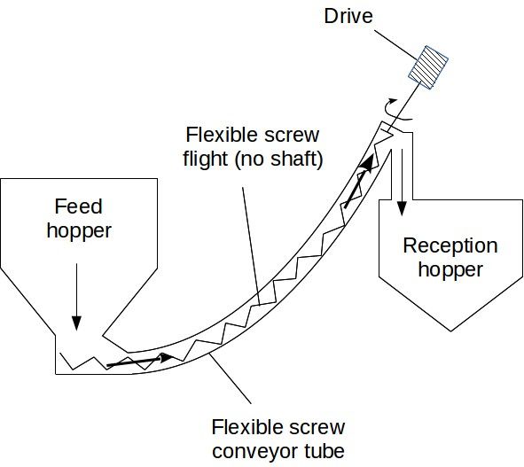
Figure 1 : principle of a flexible screw conveyor
Crucial operating dynamic: The screw flight is in direct contact with the inner wall of the plastic tube when running dry. When powder is fed, centrifugal action and mechanical displacement create a moving annular layer of bulk material between the spiral and the tube wall. This powder bed naturally centers the spiral, dramatically reducing steel-to-plastic friction and preventing wall wear.
Different spiral flight profiles are selected according to powder characteristics:
- Round spiral: Standard for free-flowing powders, pellets, and fragile granules. Low shear, lower risk of product degradation.
- Flat wire / Rectangular profile: Higher pushing surface area; ideal for light, aerated, or fluidizable powders (e.g., fumed silica, talc) and slightly cohesive materials.
- Beveled / Square edge profile: Used for smeary, sticky, or cohesive powders where positive scraping action prevents inner tube wall cake formation.
Typical design capabilities of flexible screw conveyors:
- Conveying distance: 3 to 10 m (up to 20 m with booster / tandem arrangements)
- Maximum inclination angle: up to 60° (with derated throughput)
- Tube internal diameter: 50 mm to 110 mm (common standard sizes: 65, 80, 90, 100 mm; heavy-duty executions up to 200 mm)
- Volumetric capacity: 0.5 to 15 m³/h (standard units), up to 40 m³/h in heavy-duty larger diameters
3. Interactive Sizing & Motor Power Calculator
Use this engineering sizing tool to calculate flexible screw conveyor throughput, required spiral rotation speed, inclination reduction factor, spiral tip speed, and estimated motor power.
⚡ Flexible Screw Conveyor Sizing Calculator
Shaftless Spiral Volumetric Flow, Inclination Derating & Drive PowerCalculation Results
4. Mathematical Engineering Formulas
The volumetric capacity of a shaftless flexible screw conveyor depends upon the cross-sectional area swept by the spiral flight, the screw pitch, the rotational speed, the loading degree, and the inclination angle derating factor.
1. Theoretical Swept Cross-Sectional Area \(A_{eff}\)
In a shaftless flexible screw, the core is hollow. The effective swept transport volume per pitch can be approximated through the internal tube cross-section less the hollow inner core or evaluated via total tube cross section with a practical loading factor:
\[ A_{tube} = \frac{\pi}{4} D_i^2 \]2. Volumetric Transport Rate \(Q_{th}\) & Actual Volumetric Flow \(Q_v\)
The gross theoretical volumetric conveying rate without slippage is:
\[ Q_{th} = A_{tube} \cdot p \cdot N \cdot 60 \]Accounting for the effective fill degree \(\psi\) and the gravitational inclination derating factor \(C_{inc}\):
\[ Q_v = Q_{th} \cdot \psi \cdot C_{inc} \]3. Inclination Derating Factor \(C_{inc}\)
As the conveyor inclination angle \(\theta\) increases from horizontal (\(0^\circ\)) up to \(60^\circ\), internal material back-slip increases significantly. An accurate empirical relation for coreless flexible screws is:
\[ C_{inc} = \max\left(0.15, \; \cos(\theta) - 0.28 \cdot \sin(\theta)\right) \]4. Mass Flow Rate \(\dot{m}\)
\[ \dot{m} = Q_v \cdot \rho_b \]5. Spiral Flight Peripheral Tip Speed \(v_{tip}\)
\[ v_{tip} = \frac{\pi \cdot D_i \cdot N}{60} \]6. Total Shaft Drive Power \(P_{drive}\) and Installed Motor Power \(P_{motor}\)
Drive power consists of product elevation work, frictional drag against the tube wall and spiral surfaces, and machine no-load drive losses:
\[ P_{lift} = \frac{\dot{m} \cdot g \cdot (L \cdot \sin\theta)}{3600 \cdot 1000} \quad \text{[kW]} \] \[ P_{friction} = \frac{\dot{m} \cdot g \cdot (L \cdot \cos\theta) \cdot \mu_{eff} \cdot F_m}{3600 \cdot 1000} \quad \text{[kW]} \] \[ P_{total\_shaft} = P_{lift} + P_{friction} + P_{empty} \] \[ P_{motor} = \frac{P_{total\_shaft}}{\eta_{gear}} \cdot S_f \]Where \(\mu_{eff} \approx 0.35 - 0.50\) is the equivalent internal friction coefficient, \(F_m\) is the material factor, \(\eta_{gear} \approx 0.85\) is gear reducer efficiency, and \(S_f \approx 1.25\) is an industrial motor service factor.
5. Comparison with other bulk handling systems
| Flexible Screw Conveyors | Pneumatic Conveyors | Belt Conveyors | Bucket Elevators | |
| Operating Principle | Positive displacement, rotating shaftless spiral | Pressure or vacuum-driven air/gas suspension | Continuous mechanical motion with pulleys and belt | Continuous vertical lifting via buckets attached to chain/belt |
| Design | UHMW-PE / PA tube with flexible coreless steel spiral | Rigid pipeline with blower, cyclone, and filter receiver | Flat or troughed belt running over support idlers | Vertical casing with head and boot pulleys |
| Maintenance | Moderate (low parts count; periodic tube/spiral wear check) | Moderate (rotary valves, filter bags, blowers) | Moderate to high (belt tracking, idlers, cleaner blades) | Moderate to high (chain stretch, bucket fasteners, bearings) |
| Flexibility of Layout | Relatively flexible, bends around obstacles (limited to 5-15 m) | Highly flexible routing over long distances (up to 500 m) | Fixed straight path; difficult to curve or bend | Vertical elevation only; fixed straight path |
| Dust Containment | Totally enclosed, sealed, dust-free operation | Totally enclosed, requires air filtration at discharge | Open or hooded; dust skirts and extraction needed | Enclosed casing, but aspiration required at pick-up/head |
| Material Handling Capacity | Moderate (up to 15-40 m³/h) | Moderate to high (up to 100+ t/h) | Very high (hundreds of t/h) | Moderate to high (up to 150+ m³/h) |
| Capital Cost | Low to Moderate (very economical for short transfer) | Moderate to high (blowers, filters, ATEX venting) | Moderate | Moderate to high |
⚡ Industrial Plant Engineering Best Practices & Operational Rules
- Minimum Bend Radius: Never bend a flexible conveyor tube tighter than the manufacturer's limit. A rule of thumb is a minimum radius \(R_{min} \ge 35 \text{ to } 45 \times D_{outer}\) (e.g., \(\ge 3.5 \text{ m}\) for a 90 mm tube). Forcing sharper bends creates severe localized friction and premature tube perforation.
- Never Run Dry: An empty flexible screw will generate extreme friction between the metal flight and the plastic wall. Running without powder for as little as 3–5 minutes can melt the plastic tube or produce plastic shaving contamination. Always interlock the motor with level probes.
- High-Speed Centrifugal Action: Unlike rigid screws (which run at 30–90 RPM), flexible screws require 300 to 750 RPM so centrifugal force can throw powder outwards against the tube wall, creating the lubricating product cushion that suspends the shaftless spiral.
- ATEX & Static Dissipation: In explosive dust environments (ATEX Zone 20/21/22), non-conductive plastic tubes pose serious electrostatic spark discharge risks (propagating brush discharges). Use certified antistatic carbon-loaded UHMW-PE tubes with continuity bonding wires to earth.
6. Cleaning and maintenance
How to clean a flexible screw conveyor ?
Flexible screw flights can be pulled out from the tube if the conveyor is short (under 4–5 m), although it is physically demanding when conveyor length exceeds 6 m. Practical cleaning methods include:
- Dry Purge & Reverse Discharge: Open the quick-release drop-bottom hatch at the conveyor charging adapter, then momentarily reverse the rotation at low speed. The spiral pulls residual material backwards into a container.
- Flight Extraction: Uncouple the drive shaft coupling at the discharge head, unbolt the bottom thrust bearing/plug, and pull the shaftless spiral out completely for high-pressure washing and inspection.
- Wet CIP / Flushing: Certain food and pharmaceutical configurations allow in-situ water/detergent flushing. Ensure the unit has drain ports at all low spots and operates a hot air dry cycle before reloading powder to prevent caking.
How to maintain a flexible screw conveyor ?
Over time, the plastic tube and outer edges of the spiral flight will wear due to powder abrasion. Maintenance procedures include:
- Tube Rotation: Because wear usually concentrates on the bottom arc of the tube in inclined setups, loosening tube clamps and rotating the tube by 90° to 180° every 12–18 months can double its operational lifespan.
- Spiral Inspection: Inspect spiral flight thickness. If the outer diameter wears down excessively, the clearance increases, dropping throughput and increasing material slip.
- Drive Seal Maintenance: Check the rotary shaft seal at the drive end to ensure powder has not migrated into the gearmotor bearings.
7. Flexible screw conveyors manufacturers
To obtain quotes, system pricing, or pilot plant testing for flexible screw conveyors, engineering teams can consult reputable suppliers:
- Flexicon Corporation (Pioneers of flexible screw conveying systems)
- Spiroflow (Shaftless flexible spiral conveyors)
- Hapman (Helix flexible screw conveyors)
- Solufood (Flexible screw conveying and dosing)
(Note that PowderProcess.net maintains an independent educational role and has no commercial links with these vendors.)
Frequently Asked Questions (Bulk Solids Engineering)
Top 5 Most Popular
1. Pneumatic transport design guide
2. Ribbon blenders
3. Powder mixing
4. Hoppers design guide
5. Measuring degree of mixing
--------------

--------------
Top 5 New
1. Continuous Dry Mixing
2. Mixing speed
3. Mixer cycle time optimization
4. Batch / continuous mixing comparison
5. Energy Savings