
Industrial Blenders for Powder (Batch, Convective)
Overview of Common Designs, Mixing Mechanics & Sizing Equations
Questions or remarks? Please contact us at: admin@powderprocess.net
| Section Summary |
|---|
| 1. Introduction: Mixers for Powder Blending |
| 2. Mixing Principle of Solids and Powder Blenders |
| 3. Solids Mixer Design - Mixing Tools |
| 4. Solids Mixer Design - Powder Inlet |
| 5. Solids Mixer Design - Powder Outlet |
| 6. Solids Mixer Sizing & Governing Equations |
| 7. Interactive Mixer Sizing & Froude Calculator |
| 8. Buying a Mixer: Manufacturers & Suppliers |
1. Introduction : mixers for powder blending
There are different mixer designs that can be used for dry mixing solids and make the mix homogeneous. Those different designs are at 1st based on the mixing principle, such as the V blender for diffusive mixing, or other systems where the mixing can indeed be the result of diffusion, convection and shear.
Convective mixers are actually very often used industrially since they allow usually short mixing time compared to simpler but less efficient diffusive mixer. The object of this page will therefore focus on convective mixers.
Only the case of batch mixers is discussed in this page. Such mixers are found all over industries and can handle all types of dry products :
- Agriculture / pet food : cattle feed, nutrients, grains (ribbon blender, paddle mixer)
- Food processing / baking : flour / ingredients mixing (ribbon blender, paddle mixer, ploughshare mixers)
- Dairy industries and infant nutrition : mixing base powder with minor ingredients (paddle mixer, also bin blender)
- Pharmaceuticals (paddle mixer, also tumblers)
- Construction : cements (ribbon blender, paddle mixer)
- Plastics : polymer pellets (tumblers)
- Paints : pigment mixing (ribbon blender, paddle mixer, tumblers)
2. Mixing principle of solids and powder blenders
Convective mixers are equipped with a mixing tool which is basically agitating the powder and forcing its movement.
Such solids mixers can work at different regimes which are characterised by an adimensional number, the Froude number (\(Fr\)), which compares the inertial acceleration imparted by the impeller against gravitational acceleration:
\[ Fr = \frac{\omega^2 R}{g} = \frac{v_{\text{tip}}^2}{g R} \]Where:
- \( \omega \) is the angular velocity of the impeller (\(\text{rad/s}\)), with \( \omega = \frac{2 \pi N}{60} \)
- \( N \) is the rotational shaft speed (\(\text{rpm}\))
- \( R \) is the agitator outer radius (\(\text{m}\))
- \( g \) is the acceleration of gravity (\(9.81\text{ m/s}^2\))
- \( v_{\text{tip}} \) is the agitator tip peripheral speed (\(\text{m/s}\))
When Froude is less than 1, the bed of particles will be agitated while staying relatively dense, while at more than 1 the bed of particles will be fluidized; this fluidization will increase with the Froude number.
Table 1 : Different types of powder convective mixers
| Mixer group | Froude Number (\(Fr\)) | Flow Regime |
|---|---|---|
| Ribbon blenders | \(Fr < 1\) | Dense / sub-critical convective flow |
| Screw mixers (type Nauta) | \(Fr \ll 1\) | Slow orbital convective transport |
| Vertical mixers (type Amixon) | \(Fr < 1\) | Thrust upward displacement |
| Double shaft paddle mixers | \(Fr \approx 1.0 - 1.2\) | Weightless fluidized central zone |
| Pneumatically generated fluid beds | \(Fr > 1\) | Aerated gas-solid suspension |
| Ploughshare mixers | \(Fr = 3 - 9\) | Supercritical centrifugal projection & shear |
3. Solids mixer design - Mixing Tools
The mixing tool design is particularly important in convective mixers since it provides the driving force to displace particles, ultimately reaching the desired homogeneity.
The agitator geometry and its operating speed dictate the mixing time, final coefficient of variation (\(CV\)), and potential shear-induced attrition.
Table 2 : Design of mixing tools
| Mixer type | Ribbon blender |
| Mixing tool design | Inner and outer helical ribbons pushing powder in counter-current axial directions (top view representation below):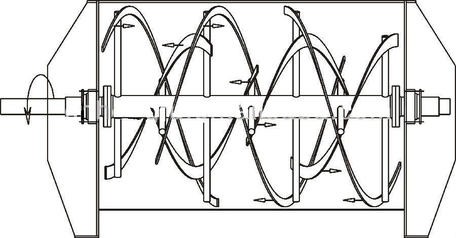
|
| Product impact | The ribbon pushes the product, meaning prolonged mixing times can cause particle attrition. Overfilling restricts free surface movement, causing severe compaction and grinding against trough walls. |
| Mixer type | Screw mixer / vertical blender (type Nauta) |
| Mixing tool design | Cantilevered screw orbiting around the perimeter of a conical vessel (side view):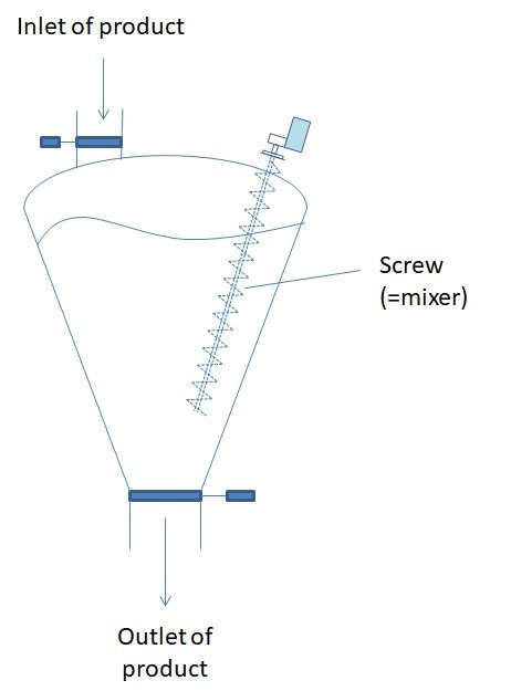
|
| Product impact | Very gentle. The screw slowly conveys material upward while precessing along the vessel wall, minimizing shear. Excellent for fragile crystals and tea leaves. |
| Mixer type | Vertical mixer (type Amixon) |
| Mixing tool design | Helical blade agitator conveying bulk material upward along the periphery and downward along the center shaft. |
| Product impact | Performs exceptionally well on cohesive and poor-flowing bulk solids compared to free-fall or simple horizontal blenders. Complete self-discharging capability. |
| Mixer type | Double shaft paddle mixer |
| Mixing tool design | Two parallel counter-rotating shafts with overlapping pitched paddles at complementary angles (typically \(45^\circ\)):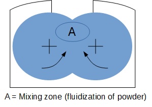
|
| Product impact | Very gentle when operated within the designated filling and speed window (\(Fr \approx 1\)). Paddles lift bulk material into a central fluidized zone where particles cross without forced contact. Rapid mixing (typically 30–90 seconds). |
| Design considerations | Radial paddle-to-trough clearance must exceed 4–6 mm to account for shaft deflection under heavy startup loads without galling the housing. Cantilevered extractable shaft designs simplify washdown in sanitary dairy/pharma plants. |
| Mixer type | Pneumatically generated fluid beds |
| Mixing tool design | No internal moving agitator. Uses compressed gas pulses directed through specialized bottom nozzles to aerate and circulate powder. |
| Product impact | Gentle, zero mechanical shear. |
| Design considerations | Requires an automated multi-valve manifold, high compressed air consumption, and robust exhaust filtration. Sensitive to percolation and elutriation segregation if particle size distribution is wide. |
| Mixer type | Ploughshare mixers |
| Mixing tool design | Single horizontal shaft with triangular ploughshare tools rotating inside a cylindrical drum, supplemented by high-speed side choppers (1500–3000 RPM):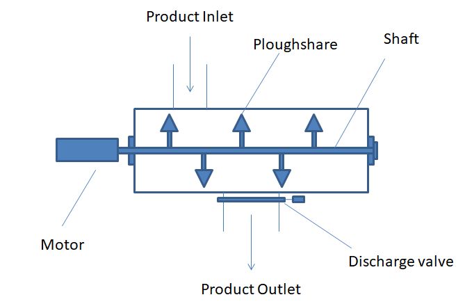
|
| Product impact | High shear and deliberate particle attrition. Ideal for dispersing sticky liquids, fat injection, breaking agglomerates, and wet granulation. |
| Design considerations | Requires heavy-duty bearings, mechanical shaft seals, and high motor installed power (up to 30 kW/m³). High tip speeds necessitate ATEX zone 20/21 spark prevention measures. |
4. Solids mixer design - Powder inlet
The powder is introduced on top of the mixer. There can be one inlet if the ingredients are preweighed in a single upstream hopper or manually tipped via a sack dump station, or multiple automated gravimetric/volumetric feed nozzles.
Inlet design considerations include:
- Inlet nozzle diameter must be sized for fast gravimetric charging to protect overall batch cycle time.
- Each port must feature an automated, dust-tight shutoff valve (pneumatic butterfly or slide gate) to isolate the mixer during processing and venting.
- Minor and micro-ingredients should always be dosed directly into the active mixing / fluidizing zone (center of the mixer) rather than stagnant corner walls.
- Mixer top covers should contain at least 1 or 2 spare blanked flanged connections for future process expansions.
- A top-mounted dedusting venting filter is required to balance displaced air during high-speed charging and admit make-up air during discharge.
5. Solids mixer design - Powder outlet
Once blending is complete, the batch must discharge rapidly to maximize system throughput. The discharge valve design must prevent dead pockets where unmixed ingredients could settle and contaminate subsequent batches.
Common discharge geometries include:
- Full-Length Bomb Doors: The bottom trough splits open entirely via pneumatic toggle cylinders. The entire batch drops into the receiving surge hopper within 5–15 seconds with negligible residual hang-up (few hundred grams). However, they require rigid structural frames and inflatable pneumatic seals to prevent fine powder leakage.
- Central Square Flaps / Slide Gates: Cost-effective and straightforward to seal. However, discharge takes longer (45–120 seconds), and slight dead zones can exist along the sealing lip.
- Flush Hygienic Disc / Spherical Valves: Offer premium cleanability and sanitary sealing (3-A / EHEDG compliance), but small discharge cross-sections can bottleneck production. Dual valves may be required on large vessels.
Operating Rule: The mixer agitator should continue turning at low crawl speed (jogging mode) during discharge to actively sweep residual powder toward the outlet gate.
6. Solids mixer sizing & Governing Equations
The mixer should act as the central pacing unit of the mixing line. The capacity of the installation is determined by required plant throughput and batch cycle logistics:
\[ M_{\text{batch}} = \frac{\dot{M}_{\text{target}}}{N_{\text{batch}}} \]Where \( M_{\text{batch}} \) is the batch mass (\(\text{kg}\) or \(\text{lb}\)), \( \dot{M}_{\text{target}} \) is the line throughput (\(\text{kg/h}\) or \(\text{lb/h}\)), and \( N_{\text{batch}} \) is the number of batches per hour (\(\text{h}^{-1}\)). Total cycle time \( t_{\text{cycle}} \) is:
\[ t_{\text{cycle}} = t_{\text{charge}} + t_{\text{mix}} + t_{\text{discharge}} + t_{\text{dead}} = \frac{3600}{N_{\text{batch}}} \]Because powder mixing is fundamentally volumetric, the working volume occupied by the batch depends strictly on the loose, aerated bulk density of the formulation:
\[ V_{\text{working}} = \frac{M_{\text{batch}}}{\rho_{\text{loose}}} \]To provide sufficient freeboard for convective circulation, particle fluidization, and lump breaking, blenders must never be filled to 100% capacity:
\[ V_{\text{total}} = \frac{V_{\text{working}}}{\eta_{\text{fill}}} \]Where \( \eta_{\text{fill}} \) is the fill fraction (typically \(0.60\) to \(0.75\), with \(0.70\) representing standard industry nominal design).
Industrial Powder Mixer Rules of Thumb & Safety Limits
- Fill Level Limits: Maximum recommended fill level is 70–75% for ribbon blenders and 60–70% for fluidizing paddle mixers. Filling beyond 80% increases mixing time by up to 300% and risks thermal degradation. Minimum fill level is 35–40% to maintain cross-trough circulation.
- Radial Clearance: Agitator outer blade-to-trough wall clearance must be set to \(3 \times d_{90}\) of the largest particle, but not less than 4–6 mm on industrial units, to prevent particle pinching and mechanical jamming.
- Tip Speed & ATEX Safeguards: Keep peripheral tip speed below \(1.0\text{ m/s}\) for ignition-sensitive, low-MIE powders (MIE < 3 mJ) to avoid static generation unless inert gas blanketing (\(\text{N}_2\)) is installed. High-shear ploughshares operate up to 2.5–4.5 m/s and require continuous bearing temperature monitoring.
- Shaft Sealing: Use air-purged labyrinth or lip seal stuffing boxes with 0.5–1.0 bar differential air pressure over the mixer internal pressure to protect bearings from abrasive dust ingress.
- Motor Sizing: Direct start of settled cohesive powders requires a 1.5 to 2.0 service factor on calculated shaft power to overcome high static yield strength at startup.
7. Interactive Solids Mixer Sizing & Froude Calculator
Size convective batch blenders (ribbon, paddle, ploughshare, Nauta) from throughput, loose bulk density, cycle parameters, and impeller geometry.
Mixer Sizing & Kinematic Outputs
8. Buying a mixer for powder blending : manufacturers of mixers
To request commercial quotes and pilot plant scale tests for powder and bulk granule mixers, consider the following established equipment manufacturers:
- Lessine : Industrial paddle blenders and dry processing equipment
- Stolz : Agricultural and food industry ribbon / paddle mixers
- Palamatic Process : Turnkey powder handling and batch mixing lines
- Sofraden : High-efficiency fluidized zone paddle and intensive mixers
- Parimix : Continuous and batch powder blending systems
- Amixon : Precision vertical twin-shaft and single-shaft sanitary conical mixers
- Hosokawa Micron : Original Nauta conical screw mixers and high-shear cyclomixers
Frequently Asked Questions: Bulk Solids Convective Mixers
How does loose bulk density affect mixer volume compared to tapped density?
Mixers must always be sized using the aerated loose (untapped) bulk density (\(\rho_{\text{loose}}\)). During convective agitation, particles dilate and entrap air. Sizing with tapped or packed density will severely under-size the required chamber volume, causing overfilling, high power spikes, and incomplete mixing.
Why do twin-shaft paddle blenders mix much faster than ribbon blenders?
Twin-shaft paddle mixers operate at a Froude number near unity (\(Fr \approx 1.0 - 1.2\)). At this speed, mechanical lifting forces exactly counterbalance gravity, lifting particles into a weightless fluidized zone in the overlapping center of the trough. In this state, particles interchange positions with minimal friction, achieving complete homogeneity in 30 to 90 seconds versus 5 to 15 minutes in a ribbon blender.
What causes mixture demixing or segregation during blender discharge?
Discharge segregation commonly occurs if the mixer empties into a central conical hopper via a restricted valve, generating funnel flow where finer particles sift through larger particles (percolation), or if free-falling materials generate air currents that elutriate light fines to the hopper perimeter. Using full-length bomb doors and mass-flow discharge hoppers prevents demixing.