
Piping diverter valves
Diverter valves in bulk solid handling (pneumatic conveying, transfer by gravity)
Follow us on Twitter

Question, remark ? Contact us at admin@powderprocess.net
| Section summary | |
|---|---|
| 1. Introduction & Requirements | 5. Flap Diverters |
| 2. Rotating Plug (Drum Diverters) | 6. Sizing Formulas & Aerodynamics |
| 3. Ball Valves | 7. Interactive Sizing Calculator |
| 4. Rotating Pipe Multi-Way | 8. Engineering Rules of Thumb & FAQs |
1. Introduction
What is a diverter valve ?
It may be necessary to have a more complex pneumatic conveying line, than a system where product is taken only from a single point A and transported only to a single point B. When there are multiple destinations and / or pick-up points, the installation of pneumatic conveying diverter valves is necessary.
Different types of diverter valves exist (see below) but all must satisfy stringent process characteristics: they must remain airtight, withstand the conveying pressure differential, provide positive shut-off to unused legs, and present no internal steps, ledges, or cavities that impede particle flow (pressure drop reduction, sanitary cleanability, preventing breakage of particles, and avoiding pipe blockages). Standard butterfly valves should be strictly avoided for inline pneumatic line routing due to severe disc wear and flow obstruction.
2. Rotating plug (or drum diverters)
Such valves are equipped with an internal cylindrical or conical plug insert with a precision-machined bore matching the conveying line pipe diameter. The rotation of this plug within an outer housing allows the flow to be directed smoothly from an inlet to one of two (or three) outlet branches, typically oriented at a diversion angle of \(30^\circ\) or \(45^\circ\).
Drum diverter valves are highly hygienic and sanitary since, well operated, their continuous full-bore design prevents powder retention or dead pockets. Standard industrial plug diverters can withstand conveying pressures of 3 to 6 bar g (45 to 90 psig), making them the gold standard for both dilute phase and high-pressure dense phase systems.
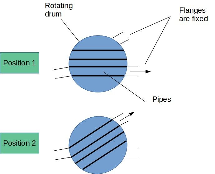
The design of the seal is paramount for durability and ensuring zero bypass leakage during pneumatic transport. Modern industrial drum diverters incorporate inflatable pneumatic seals. When the valve spools into position, compressed air inflates silicone, EPDM, or Viton seals against the rotor to ensure 100% pressure-tight sealing. Prior to rotation, the seals automatically deflate to create physical running clearance, completely preventing seal abrasion and actuator overload during movement.
3. Ball valves
Contrary to rotating plug diverters, a distribution setup using ball valves requires the installation of two separate valves in a branching 'Y' or 'T' pipe tee configuration—one valve on each branch.
Standard industrial ball valves are known to retain powder between the spherical ball and the outer valve body cavity. While cavity-filled Teflon gaskets can be specified for sanitary service, a fundamental operational drawback remains: the dead-leg piping stub located immediately upstream of the closed ball valve fills with stagnant powder during conveying. When flow is later switched to that branch, packed solids can surge into the receiver or cross-contaminate different powder grades. Ball valves should only be used where cross-contamination is non-critical and system pressure is high.
4. Rotating pipe (multi-port distributors)
Rotating pipe diverters provide a cost-effective, compact solution when distributing bulk solids from one source to many destinations (e.g., supplying a battery of 4 to 12 storage silos or compounding feed hoppers). A central swiveling pipe rotates around an indexed arc to align mechanically with an array of fixed outlet flanges.
Because sealing across multiple rotating joints is mechanically complex, rotating pipe distributors are generally restricted to low-pressure dilute phase conveying (typically \(< 1.0\text{ bar g}\)). They require automated clamping collars or inflatable seals at each docking position to prevent ambient dust leakage.
5. Flap diverter valves
A flap diverter utilizes an internal hinged vane or flap blade swinging between two discharge legs of a cast 'Y' body. This is mechanically the simplest and most economical diverter design.
However, flap diverters should be considered only in gravity drop transfer or extremely low negative-pressure lines (\(< 0.1\text{ to }0.2\text{ bar}\)). Because the swinging blade cannot achieve a positive pressure seal against fine particles, using a flap valve in positive pneumatic conveying invariably leads to severe air bypass, product leakage into the wrong silo, and rapid abrasive cutting across the flap edge.
Top 5 Most Popular
1. Pneumatic transport design guide
2. Ribbon blenders
3. Powder mixing
4. Hoppers design guide
5. Measuring degree of mixing
--------------

--------------
Top 5 New
1. Continuous Dry Mixing
2. Mixing speed
3. Mixer cycle time optimization
4. Batch / continuous mixing comparison
5. Energy Savings
6. Pneumatic Diverter Aerodynamics & Pressure Drop Physics
Sizing a pneumatic diverter valve requires evaluating the local superficial air velocity, solid loading ratio, and localized two-phase pressure drop. A diverter must match the internal diameter of the incoming pipe to prevent expansion steps (which trigger saltation drop-out) or contraction nozzles (which cause choking and localized abrasion).
6.1 Superficial Gas Velocity
The operating superficial conveying air velocity \(v\) at the diverter location is determined by the local volumetric air flow rate \(Q_{actual}\) and the valve bore cross-sectional area \(A\):
\[ v = \frac{4 \cdot Q_{actual}}{\pi \cdot D^2} \]where \(Q_{actual} = Q_0 \cdot \frac{P_0}{P} \cdot \frac{T}{T_0}\), \(D\) is the inside bore diameter, \(P\) is the absolute line pressure at the valve, and \(T\) is the operating absolute temperature.
6.2 Solids Loading Ratio
The solids mass loading ratio \(\mu\) reflects the mass of powder conveyed per mass of transport gas:
\[ \mu = \frac{\dot{m}_{solids}}{\dot{m}_{gas}} = \frac{\dot{m}_{solids}}{Q_{actual} \cdot \rho_{gas}} \]6.3 Two-Phase Pressure Drop Across Diverter
The localized pressure drop across a diverter valve accounts for the flow deflection angle and particle re-acceleration through the junction:
\[ \Delta P_{valve} = \Delta P_{gas} \cdot (1 + K_s \cdot \mu) = K_0 \cdot \frac{1}{2}\rho_{gas} v^2 \cdot (1 + K_s \cdot \mu) \]where \(K_0\) is the clean-gas loss coefficient of the diverter geometry (\(\approx 0.35\) for a \(30^\circ\) plug diverter, \(\approx 0.50\) for a \(45^\circ\) plug diverter, \(\approx 0.85\) for a ball valve tee branch), and \(K_s\) is the solids acceleration factor (typically \(0.3 \text{ to } 0.5\) for dry powders).
6.4 Equivalent Pipe Length
The diverter can also be expressed as an equivalent length of straight conveying pipe \(L_{eq}\):
\[ L_{eq} = \frac{K_0 \cdot D}{f_D} \]where \(f_D\) is the Darcy friction factor (\(\approx 0.018 - 0.022\)).
7. Interactive Diverter Valve Sizing Calculator
Use this engineering tool to calculate operating velocity, solid loading ratio, two-phase localized pressure drop, and check suitability against industrial limits.
Pneumatic Diverter Sizing Tool
Calculation Results Summary
8. Practical Plant Engineering Rules of Thumb & Safety Limits
Industrial Diverter Valve Best Practices
- Purge Cycle Interlock: Never actuate a standard diverter while solids are in motion. Implement a mandatory PLC sequence: shut off upstream powder feeding, continue conveying air for 15–30 seconds to clean the pipe, verify line depressurization, actuate diverter, confirm limit switch feedback, and then restart powder feed.
- Inflatable Seal Pressure Monitoring: Always install dual pressure switches on the seal air supply. Diverter inflatable seals must operate at least 1.5 to 2.0 bar (22 to 30 psi) above conveying line pressure. Conveying must automatically trip if seal inflation pressure falls below setpoint.
- Angle Optimization (30° vs 45°): For fragile pellets (e.g., polymers) or abrasive materials (e.g., alumina, silica), select a \(30^\circ\) divergence angle rather than \(45^\circ\). The reduced impingement angle cuts localized wear rates by over 50% and minimizes angel-hairing/streamers.
- ATEX & Grounding Continuity: When routing through hazardous dust zones (ATEX Zone 20/21/22), ensure the rotating plug or drum is bonded to ground using high-flex copper bonding straps or certified conductive carbon brushes. Standard ball bearings do not provide reliable ground paths and can cause electrostatic spark ignition.
- Differential Pressure Rating: Check valve differential pressure rating. High-pressure dense phase systems (2–6 bar g) require precision machined cast housings with metal-to-metal or inflatable elastomeric seating. Flap valves must be strictly restricted to gravity chute installations.
Frequently Asked Questions (FAQ)
Q1: Can a diverter valve be switched while powder is flowing through the line?
In standard industrial practice, rotating drum or plug diverter valves should never be actuated during active powder flow. The conveying stream should be stopped and the line cleared with pure conveying air for 15 to 30 seconds before switching ports. Actuating while solids are moving causes severe abrasive wear, seal gouging, particle degradation, and actuator stalling. Only specially engineered high-pressure shear diverters with hardened knife-edge gates are rated for dynamic on-the-fly switching.
Q2: Why are flap diverters unsuitable for pressure pneumatic conveying lines?
Flap diverter valves rely on a swinging blade sealing against a polyurethane or metal seat without compressive mechanical latching or inflatable bladder assist. In a pressurized pneumatic system (> 0.2 bar g), air bypass carries fine particles through the closed leg, creating severe cross-contamination, erosion along the blade edge, and significant conveying pressure loss. Flap valves should be strictly reserved for gravity transfer chutes.
Q3: How do inflatable seals function on high-pressure rotating plug diverters?
Inflatable seals work via an automated sequential PLC interlock. During active conveying, compressed air inflates elastomeric seals (EPDM, silicone, or fluoroelastomer) to 1.5–2.0 bar above conveying line pressure, ensuring a gas-tight, dust-tight seal. Before the drum rotates to a new port, the seal is completely vented and retracted to create radial clearance, allowing frictionless rotation without dragging or tearing. Once in position, the seal re-inflates before powder feeding resumes.