
Weighing & Batching : Powder Dosing
Powder and bulk solids dosing systems in process industries
Follow us on Twitter 
Question, remark ? Contact us at admin@powderprocess.net
| Section summary |
|---|
| 1. Principles of dosing |
| 2. Interactive Dosing & Batching Calculator |
| 3. Feeding equipment |
| 4. Best Practices & Engineering Rules of Thumb |
| 5. Tips for good dosing & troubleshooting |
Principles of dosing : how to dose powders
An essential component of any weighing system is the Load Cell. The load cell will measure the force applied and translate it to a weight that is readable by the user and can be used for running the process.
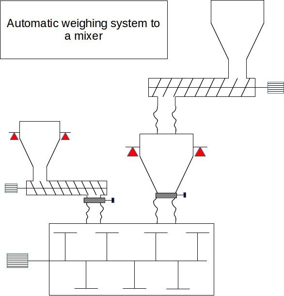
Figure 1 : example of automatic powder weighing system
This section touches 2 main ways to dose found in the industry : Gain-in-Weight dosing and Loss-in-Weight dosing. The key difference in between those 2 dosing approaches is the position of the load cells.
Gain-in-Weight dosing (GIW)
The dosing Gain-in-Weight is done by measuring weight of a hopper located after the dosing instruments. It is somehow similar to what many cooks do in the kitchen when they weigh on a scale the quantity of product required for their recipe.
Several ingredients from several hoppers can be dosed to the hopper on Load Cells. A restriction is however that the dosing must be sequential. Since the weight is measured by the hopper downstream, if all ingredients are dosed at the same time, the dosing cannot be tracked individually. On the other side, such sequential dosing can be done in advance while the rest of the process after the dosing hopper is occupied performing other tasks. It is called dosing in hidden time.

Figure 1 : Dosing principle for a Gain in Weight system
Loss-in-Weight dosing (LIW)
Contrary to GIW dosing, the hopper on load cells driving the dosing is located above the dosing instrument. It means that, when the dosing instrument runs and delivers the product, the weight of the hopper from which the product is taken is decreasing—it is losing weight.
It means that different dosing to the same equipment (a mixer for example) can be performed independently, representing a gain of time. On the other hand, the dosing cannot easily be performed in hidden time unless an intermediate surge bin is placed below. Combining the advantages of both techniques (LIW and GIW) requires more headroom and structural complexity, but solves batch bottleneck issues.
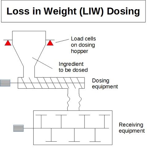
Figure 2 : Dosing principle for a Loss in Weight system
Continuous dosing
By its nature, Gain-In-Weight dosing is a batch operation and therefore cannot be applied directly for continuous dosing. Wherever continuous dosing is required (feed of a continuous mixer or extruder), it must be performed using Loss-In-Weight feeders. Such applications require advanced PLC/DCS algorithms to handle gravimetric control and filter out mechanical disturbances on the load cells during periodic hopper refill cycles.
Interactive Powder Dosing & Batching Calculator
Use this interactive tool to design and optimize coarse/fine batch dosing schedules, calculate in-flight material compensation, estimate batch cycle times, and verify scale load cell capacity utilization.
Batch Dosing Results Summary
Key Governing Equations for Powder Dosing
Mathematical modeling of powder dosing requires accounting for phase durations, gravitational drop times, and actuator closure delays:
1. Total Active Feed Time Formula:
\[ t_{\text{feed}} = t_{\text{coarse}} + t_{\text{fine}} = \frac{M_{\text{target}} \cdot P_{\text{coarse}}}{\dot{m}_{\text{coarse}}} + \frac{M_{\text{target}} \cdot (1 - P_{\text{coarse}})}{\dot{m}_{\text{fine}}} \]2. Free-Fall In-Flight Mass Formula:
\[ t_{\text{flight}} = \sqrt{\frac{2 h}{g}} \] \[ M_{\text{inflight}} = \dot{m}_{\text{fine}} \cdot \left( t_{\text{valve}} + \sqrt{\frac{2 h}{g}} \right) \]3. Scale Utilization Percentage:
\[ U_{\text{scale}} = \frac{M_{\text{tare}} + M_{\text{target}}}{N_{\text{cells}} \cdot C_{\text{cell}}} \times 100\% \]Where \(M_{\text{target}}\) is target mass, \(\dot{m}\) is mass flow rate, \(P_{\text{coarse}}\) is coarse feed fraction, \(h\) is drop height, \(g\) is gravitational acceleration (\(9.81 \text{ m/s}^2\)), \(t_{\text{valve}}\) is valve closing time, \(N_{\text{cells}}\) is load cell count, and \(C_{\text{cell}}\) is cell rated capacity.
Dosing (feeding) Equipment
Table 1 : List of common dosing equipment
| Equipment | Application |
|---|---|
| Screw feeder | Screw conveyors are one of the most common and simple ways to perform a dosing. It can be used both in LIW and GIW, can have different sizes. The design of the powder inlet as well as the screw flight pitch is of importance to manage to perform a quick and precise dosing. |
| Vibrating tubes | Vibrating tubes have the advantage to be gentle with the product, easy to clean and maintain and can reach high throughput. The inertia experienced at the end of dosing makes it however more difficult to control to get a right precision. It should therefore be reserved for major ingredients. |
| Airlock rotary Valve | Airlock rotary Valves can be used for dosing but do not constitute a preferred solution. It is difficult to reach a good accuracy and these equipment are expensive to buy and complex to maintain. It must be reserved for very specific applications (e.g. ATEX pressure containment barriers). |
| Vibrating valve | Some suppliers can propose a butterfly valve equipped with a special actuator that controls the flux of product by vibrating. This kind of dosing offers a compact solution that can be used for major / minor ingredients. |
| Loss In Weight Feeders | Loss in Weight Feeders refer to special machines built under the LIW model that come standalone with their own controller. They are used mainly for ingredients requiring a very high degree of accuracy and can have a specific design to adapt to the characteristics of each ingredient (twin screw, agitated hopper...). Such systems are also used in continuous dosing. |
Top 5 Most Popular
1. Pneumatic transport design guide
2. Ribbon blenders
3. Powder mixing
4. Hoppers design guide
5. Measuring degree of mixing
--------------
 --------------
Top 5 New
1. Continuous Dry Mixing
2. Mixing speed
3. Mixer cycle time optimization
4. Batch / continuous mixing comparison
5. Energy Savings
Industrial Powder Dosing Rules of Thumb & Safety Best Practices
- Coarse to Fine Speed Ratio: Maintain a 5:1 to 10:1 ratio between coarse dosing rate and fine dribble dosing rate for optimal balance between accuracy and cycle speed.
- Scale Load Cell Utilization: Design system scale capacity so that maximum gross mass (tare + full target batch) operates between 30% and 80% of rated capacity. Operating below 15% degrades load cell resolution; operating above 85% risks mechanical overload from drop impact.
- In-Flight Material Compensation: Implement dynamic auto-preact algorithms in the weigh controller to dynamically subtract the in-flight column mass \(M_{\text{inflight}}\) prior to valve cut-off.
- Vibration & Isolation: Use high-flexibility, non-restraining sleeve connections (e.g. silicone or BFM fittings) between weighing hoppers and adjacent stationary piping. Never allow rigid conduit or pneumatic hoses to bridge across load cell scales.
- Venting & Dust Control: Discharging powder into a closed hopper generates air pressure spikes that load cells misinterpret as mass. Ensure hoppers are equipped with properly sized reverse-jet dust filters or passive balance lines.
Achieving a good dosing : common issues in powder dosing and how to fix it
The key in achieving a good dosing is mainly in the care applied to properly isolate the load cells from any disturbance of the environment. Of course, the basics is to have load cells correctly calibrated and giving weights within the limits defined by the supplier. However, if a disturbance happens, the load cells will read an inaccurate weight but will anyway give a value : this is where it can be tricky for the plant operator—can the value be trusted or not?
To trust the value, it is necessary to ensure that no force, except those due to the weight measured, applies to the load cells. It is particularly important to make sure the following parameters are strictly maintained.
Table 2 : Key parameters to achieve an accurate dosing
| Parameter | What to do |
|---|---|
| Flexible connections | The flexible connections are neither too tensed nor too compressed. This is particularly important to check after maintenance, cleaning, or pipe alignment. |
| Filters | Discharging a powder induces air displacement. If air is not properly vented (downstream hopper) or admitted (upstream hopper), the air pressure pushes on the hoppers and disturbs load cell readings. Ensure filter vents are unblocked and properly sized. |
| External disturbances | Ensure no vibration is transmitted to the scale during dosing (e.g. from nearby shakers or heavy motors), no operator rests on the hopper, and no strong HVAC air draft impacts the structure. |
| Other connections | Ensure electric cables, air supply lines, and safety stays do not prevent the scale hopper from moving freely along its measurement axis. |