
Pneumatic Conveying Bends
Design, Pressure Drop, Material Attrition, and Wear Optimization in Piping Bends and Elbows
For detailed pressure drop calculations across entire conveying lines, please visit our Pneumatic Conveying Handbook.
Question or remark ? Please contact us at admin@powderprocess.net
| Section summary |
|---|
| 1. Introduction |
| 2. Bend Design Options |
| 3. Process Effects of Bends |
| 4. Interactive Bend Pressure Drop Calculator |
| 5. Solving Problems Linked to Bends & Best Practices |
| 6. Frequently Asked Questions (FAQ) |
1. Introduction
Bends in Pneumatic Conveying lines are necessary; it is extremely rare to have a purely straight pipe route between a pickup point and a receiving vessel. However, bends introduce directional changes that dissipate kinetic energy, cause material deceleration, and generate substantial wear or particle breakage if not properly sized.
Shortly after installing a new conveying line, the following operational issues frequently occur when bends are misconfigured:
- The line undergoes choking or frequent blockages.
- Pressure drop is higher than calculated, severely throttling overall transport capacity.
- Conveyed solids experience attrition, fines formation, or surface smearing ("angel hair").
- Localized powder build-up occurs downstream of elbows.
These severe problems can be systematically prevented by optimizing the Conveying Pipe layout, adjusting bend radius ($R/D$), and respecting key acceleration distances.
2. Bend Design Options
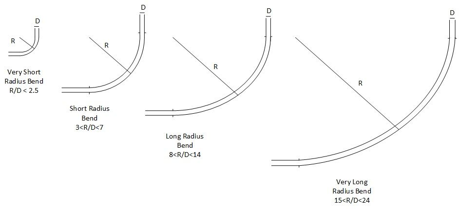
Bends come in a wide range of geometries, from sharp short-radius elbows (tee bends) to long-radius sweeps and patented pocketed elbows. The table and figures below detail common bend styles, illustrating their relative merits and design tradeoffs.
Top 5 Most Popular
1. Pneumatic transport design guide
2. Ribbon blenders
3. Powder mixing
4. Hoppers design guide
5. Measuring degree of mixing
Top 5 New
1. Continuous Dry Mixing
2. Mixing speed
3. Mixer cycle time optimization
4. Batch / continuous mixing comparison
5. Energy Savings
Figure 1 : Regular Bend Radius Styles
| Type of Bend | Ratio R/D | Engineering Remarks |
|---|---|---|
| Very Short Radius | R/D = 1.0 to 2.5 | Sharp elbow design. Results in severe localized particle fragmentation, accelerated wall wear for abrasive solids, and high pressure drop. Used only where layout space is strictly restricted. |
| Short Radius | R/D = 3.0 to 7.0 | Sharp bend transition. Significant particle breakage and wall wear risk. Suitable when spatial footprint requires tight routing, provided material is non-fragile and non-abrasive. |
| Long Radius | R/D = 8.0 to 14.0 | Optimal engineering compromise balancing space, low pressure drop, component longevity, and product protection for general powders. |
| Very Long Radius | R/D = 15.0 to 24.0 | Often assumed to minimize breakage, but long sliding contact causes repeated particle bounce/friction. In plastic pellet conveying, it causes localized surface melting, forming unwanted "angel hair" streamers. |
| Proprietary / Pocketed Design | Usually short radius footprint | Incorporates internal pockets (e.g. blind tee or Gamma bend) where a stationary cushion of powder forms. Particles impact powder rather than metal, drastically reducing erosion and attrition. Less suitable for hygienic food/pharma due to cleanability constraints. |
Table 1 : Comparison of Piping Bend Geometries
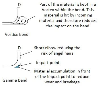
Figure 2 : Specialized / Proprietary Bend Designs
3. Process Effects of Bends
In dilute-phase and dense-phase pneumatic transport systems, bends induce major fluid dynamic and mechanical losses:
- Pressure Drop & Solid Re-acceleration: As gas-solid suspension enters an elbow, particles lose forward velocity due to friction and centrifugal impact against the outer wall. Downstream of the bend, gas expansion energy must re-accelerate particles back to gas speed. This energy loss is modeled by: \[\Delta P_{\text{bend}} = N_{\text{bend}} \cdot \left( K_g + K_s \cdot \mu \right) \cdot \frac{1}{2} \rho_g U_g^2\] where \(K_g\) is gas resistance factor, \(K_s\) is solid resistance factor, \(\mu = \frac{\dot{m}_s}{\dot{m}_g}\) is solids loading ratio, \(\rho_g\) is gas density, and \(U_g\) is superficial gas velocity.
- Pipe Blockage Risk: If line pressure drop across bends exceeds available blower differential or if gas velocity drops below saltation velocity, solids settle out and trigger total line blockages.
- Product Attrition: Solid particles striking the outer elbow radius absorb impact kinetic energy: \[E_k = \frac{1}{2} m_p U_g^2 = \frac{1}{12} \pi d_p^3 \rho_p U_g^2\] High kinetic energy leads to crystal fracture, particle degradation, and fines creation.
- Pipe Erosion & Wear: Abrasive particles (e.g., silica sand, fly ash, alumina) cut into elbow metal, requiring expensive wear-resistant alloys or ceramic backings.
4. Interactive Bend Pressure Drop & Attrition Calculator
Estimate the pressure drop across bends, single-particle impact energy, solids loading ratio, and minimum pickup distance using the engineering tool below.
5. Solving Problems Linked to Bends & Engineering Rules of Thumb

Figure 3 : Particle Flow Pattern and Wall Collision Dynamics in Pipe Bends
💡 Practical Engineering Rules of Thumb for Conveying Bends
- Acceleration Distance: Never place an elbow immediately downstream of a rotary valve, blow tank, or pickup shoe. Always provide at least 2.5 to 3.0 meters (10D to 20D) of straight horizontal pipe to accelerate solids up to conveying speed before turning.
- Spacing Between Bends: Maintain a minimum straight distance of 10 to 15 pipe diameters between consecutive bends. Back-to-back elbows create compounded turbulence and severe pressure spikes.
- End-of-Line Velocity Control: Because gas expands as pressure drops along the line, gas velocity is highest near the receiving filter/cyclone. Avoid putting short-radius elbows near line discharge where particle kinetic energy ($E_k \propto U^2$) is maximum.
- ATEX & Grounding Continuity: All metallic pipe bends must be bonded and grounded across flexible couplings with copper jumpers ($\le 10^6\ \Omega$ resistance) to eliminate static discharge ignition risks in dust explosion zones.
| Operational Issue | Root Cause & Recommended Actions |
|---|---|
| Line Blockages at Bends |
1. Verify acceleration length: ensure 2 to 3 m minimum straight pipe after pickup point. 2. Avoid back-to-back consecutive elbows without straight re-acceleration runs. 3. If saltation occurs in oversized long sweeps, switch to short-radius elbows (R/D = 3 to 5) to shorten deceleration zone length. |
| Excessive Total Pressure Drop |
1. Simplify routing layout: reduce total number of 90° bends. 2. Replace short-radius elbows (R/D < 3) with standard long-radius sweeps (R/D = 8 to 12) where space allows. 3. Increase line diameter if superficial gas velocity exceeds 28–30 m/s. |
| Particle Attrition & Degradation |
1. Reduce gas velocity down closer to minimum saltation limit. 2. Use pressure conveying instead of vacuum transport to minimize high end-of-line pickup velocities. 3. Consider dense-phase pneumatic conveying ($U_g = 3 - 8 \text{ m/s}$) to reduce particle impact kinetic energy by over 80%. |
| Severe Bend Erosion / Wear |
1. Install ceramic-lined, hardened alloy, or heavy-wall reinforced steel bends. 2. Specify dynamic pocketed bends (blind tees or Gamma elbows) to form a protective powder impact cushion. 3. Transition from dilute-phase high-velocity transport to low-velocity dense phase. |
6. Frequently Asked Questions (FAQ)
Q: How does bend radius ratio (R/D) affect overall system pressure drop?
A: Short radius bends (R/D = 1.5–3) force rapid momentum dissipation, creating localized high pressure drop per elbow. Standard long-radius bends (R/D = 8–12) reduce solid impact loss and lower total resistance. However, excessively long sweeps (R/D > 15) add extra wall friction length that offsets directional gains.
Q: Why should elbows be avoided immediately following feeding points?
A: Solids enter the pipe at low velocity and need distance to accelerate. Placing an elbow directly after a pickup shoe forces slow, dense powder into wall impact, causing saltation, severe pressure spikes, and line plugging.
Q: What causes "angel hair" in polymer pellet conveying lines?
A: Plastic pellets sliding along long-radius bend outer walls generate frictional heat. The friction melts pellet surfaces, leaving thin plastic films. As these films peel off, they form ribbons or "angel hair". Using shorter radius bends or specialized pocketed elbows prevents continuous sliding friction.
References & Sources
1. Dhodapkar, Solt, Klinzing, Understanding Bends in Pneumatic Conveying Systems, Chemical Engineering, April 2009.
2. Hilbert, Pneumatic Conveying Line Design Criteria, Powder and Bulk Engineering, March 2017.