
Piping : Pneumatic conveying pipe & Bend Sizing Guide
For calculating pressure drop in conveying pipe, please visit our pneumatic conveying handbook
Follow us on Twitter
Question, remark ? Contact us at admin@powderprocess.net
| Section summary |
|---|
| 1. Introduction |
| 2. Piping connections / coupling |
| 3. Piping bends |
| 4. Piping length |
| 5. Pressure and vacuum service |
| 6. Flexibles |
| 7. Interactive Pipe & Bend Sizing Calculator |
| 8. Plant Engineering Rules of Thumb & Limits |
1. Introduction
Conveying pipes are used in pneumatic conveying to send the product from a point A to a point B. There design is resulting from the considerations of different inputs or constraints.
Among the constraints are the aspects related to the performance of the conveying system and its influence on products. This will fix the pneumatic conveying pipe diameter but also the design of the bends of the pipe layout.
Some inputs will have also to be done by the plant operator, especially regarding the type of pipe coupling (clamping) to be used or the length of pipe sections. The material of the conveying tubing must also be chosen, it can be a standard carbon steel for non sensitive industries (polymer...) or stainless steel (food industries).
2. Pneumatic Transport Piping connections
How to best chose the pipe coupling ? Pros and cons of each type of coupling ?
Different types of pneumatic conveying pipe couplings are available in the market. The main ones are the following :
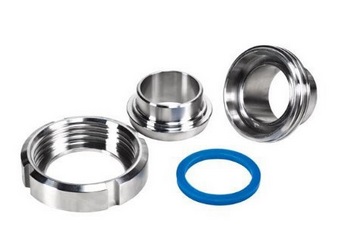
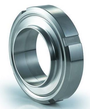
- SMS connections (and variations like DIN coupling)
- Morris clamps
- Flanges
The decision to go for one or the other will depend on the service conditions of the pneumatic conveying line, the habits of the plant operator but also the confidence on the reliability of the conveying line - if the product to be transported is very difficult and blockages are expected, it is better to have quick dismantling connections.
Table 1 : Different types of piping connections and their advantages and drawbacks
| Type of coupling | Picture | Pros | Cons |
|---|---|---|---|
| SMS (and variations like DIN) |
|
Quick dismantling Easy to dismantle and clean the pipe |
More expensive - need to have threaded pipes Sometimes difficult to have a tight connection |
| Morris coupling | 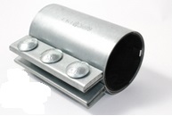 |
Less sensitive to pipe alignement vs SMS Generally tight No need to have threaded pipe |
Long to dismantle Not always easy to adjust |
| Flange | 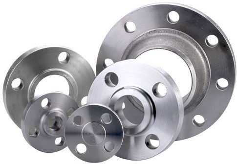 |
Tighter connection, can be qualified for high pressures Long lasting - usually preferred when the pipes goes over long distance outside building |
Very Long to dismantle Not always easy to adjust Need to change the gasket at each opening |
3. Pneumatic conveying pipe bends
How to design at best conveying pipe bends ?
The design of Conveying Pipe Bends is of particular importance for lean phase conveying where the product is circulated at high velocity. When hitting the pneumatic conveying elbows some products will be damages - fragiles powder breaking and forming fines.
In order to avoid such phenomena, the pneumatic transport bend radius must not be too sharp. As a general rule, the ratio Bend Radius / Pipe diameter should not be below 10:
4. Piping length
Deciding on the pipe section length will mainly depends on the service which is expected for the pipe. If it is expected to be dismantled often for cleaning for example, then short pipe sections are recommended. On the contrary, if the system is not expected to be dismantled, while conveying a single and well known product for instance, then it will be economically sounder to have longer sections.
As a rule of thumbs :
- High frequency for dismantling : pipe section length < 6 m (can be as low as 2 m)
- No dismantling expected : pipe section > 10 m
When having to dismantle pipes frequently, specific access may be foreseen in order to ensure a safe access to the piping.
5. Pressure and vacuum service
The pressure at which will be operated the pipe must be taken into consideration for the choice of the piping but also the coupling required. Although pressure in conveying line is usually moderate, it is a good engineering practice to define the maximum pressure that could happen, especially in case of problem on the line, and chose piping and coupling qualified for a higher pressure.
A proper installation of the coupling is also critical for both pressure and vacuum service. It is important to avoid leakages of product in the case of pressure conveying, which would lead to losses but also to dust explosion risks. For vacuum conveying ingress of air in the pipe must be avoided as it could bring pollutants if the air is not treated or which could reduce the performance of the conveying line by bypassing the inlet of product and reducing the conveying air available at the beginning of the line potentially leading to blockages of the pipe.
6. Flexibles
Short flexible sections can be used in pneumatic conveying lines especially when connecting to hoppers on load cells where the hoppers should be free of movement in order to have an accurate weighing.
It is also possible to use pneumatic conveying hoses in certain circumstances to conveying pneumatically materials. It is for example the case when discharge a truck tanker by pneumatic conveying : the truck is connected to the conveying pipe thanks to a flexible pneumatic transfer hose, whose material must be strong enough to resist to the wear induced by the material flow. When using a long flexible hose, it is important to ensure it somehow remains straight, as a very curvy tubing will lead to high pressure drop in the conveying line.
7. Interactive Pneumatic Conveying Pipe & Bend Sizing Tool
Use this calculator to compute superficial conveying gas velocity, actual operating flow, solids loading ratio, bend radius compliance, and equivalent piping length.
Calculation Summary
| Parameter | Value | Design Criterion / Guidance |
|---|---|---|
| Actual Superficial Gas Velocity (\(v_{\text{gas}}\)) | -- | Dilute phase typical: 18 – 25 m/s |
| Actual Volumetric Gas Flow (\(Q_{\text{actual}}\)) | -- | Corrected for operating P & T |
| Solids-to-Gas Mass Ratio (\(\mu\)) | -- | Dilute: < 15 kg/kg | Dense: > 25 kg/kg |
| Bend Radius Ratio (\(R_{\text{bend}} / D_{\text{pipe}}\)) | -- | Recommended: \(\ge 10\) to avoid excessive attrition |
| Recommended Min. Bend Radius (\(R_{\text{rec}}\)) | -- | Based on \(10 \times D_i\) rule of thumb |
| Equivalent Length of Bends (\(L_{\text{eq, bends}}\)) | -- | Empirical allowance (~30 \(D_i\) per bend) |
| Total Equivalent Pipe Length (\(L_{\text{total}}\)) | -- | Straight length + Bend equivalent allowances |
8. Practical Plant Engineering Rules of Thumb & Safety Limits
Key Piping & Layout Best Practices
- Avoid Back-to-Back Bends: Always leave a minimum straight spool of \(10 \times D_{\text{pipe}}\) (or at least 1.5 to 2 meters) between two consecutive 90° bends. Placing bends directly in series prevents particle re-acceleration and drastically increases localized pressure drop.
- Do Not Locate Bends Directly After Feeders: Ensure a minimum straight run of 3 to 5 meters immediately after rotary valves, venturis, or blow-through pots to permit particles to accelerate to their terminal velocity before negotiating their first turn.
- ATEX & Grounding / Bonding: Every pipe section connected with non-conductive sleeve couplings (like rubber-gasketed Morris clamps) must be electrically bonded with continuous braided copper straps to avoid electrostatic charge accumulation.
- Flexible Sleeve Restraints: For weighing hoppers on load cells, ensure flexible sleeves are installed axially unstressed, without tight hose clamps binding against hopper structure, and use conductive FDA-approved silicone or polyurethane with integral grounding bridges.
- Inclined Piping Avoidance: Avoid running pipes at angles between 15° and 75° from horizontal. Particles tend to slide back against air flow on inclined surfaces, causing unstable slugging and line choking. Transition strictly from horizontal to vertical.
Frequently Asked Questions (FAQ)
Why is the bend radius ratio (R/D) kept at 10 or greater?
In dilute phase conveying, particles impact outer elbow surfaces at high velocity. A long radius (\(R/D \ge 10\)) ensures shallow impact angles, spreading particle impingement across an elongated arc and reducing impact kinetic energy, fines creation, polymer streamer (angel hair) formation, and tube blowout.
When should Morris clamps be selected over welded flanges?
Morris couplings are standard for low to moderate pressure pneumatic systems (typically up to 1 barg or vacuum) inside plant buildings. They allow rapid assembly, absorb slight thermal expansions and angular misalignments, and avoid high fabrication costs associated with weld necks or raised face flanges.
How do flexible sleeves affect load cell weighing accuracy?
A flexible connector exerts a small spring rate and an effective pressure area force (\(\Delta P \times A\)). To prevent weighing errors, flexible sleeves should be short, flexible, mounted horizontally or with roll bellows, and have sufficient radial slack so they do not exert vertical mechanical thrust on the weigh hopper.
Top 5 Most Popular
1. Pneumatic transport design guide
2. Ribbon blenders
3. Powder mixing
4. Hoppers design guide
5. Measuring degree of mixing
--------------

--------------
Top 5 New
1. Continuous Dry Mixing
2. Mixing speed
3. Mixer cycle time optimization
4. Batch / continuous mixing comparison
5. Energy Savings